Shape Builder
What it is ℹ️
Draw primitives and custom geometry directly in the viewport with live previews, snapping, and precise controls.
When to use 🧩
- Blocking out levels and paths
- Creating walls, floors, ramps, stairs, wedges, cylinders, sectors, and spheres
- Drawing smooth curves for roads, rails, pipes, and organic shapes
- Laying out connected segment paths — roads, walls, fences, and curbs — with shaped corners (Line)
- Making clean, repeatable geometry with consistent dimensions
Workflow 🛠️
- Choose a shape and draw mode in the panel.
- Enable grid or surface snapping as needed.
- Click in the viewport to place points.
- You will see a preview as you set points.
- You can change settings while placing points. The preview updates accordingly.
- Building will end after placing the last point.
- You have created a shape.
The points you've placed stay exactly where they are, but the plugin lets go of the mouse so you can change settings, move the camera and click around Studio without a stray click landing in your build. Press Shift+P again (or the Resume button on the paused badge) to carry on from where you stopped. What is frozen on screen is what you get: change a setting while paused and the frozen preview follows it, and finishing from there builds the shape you are looking at.
Supported shapes

Shape - Block
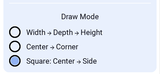
Draw Modes
Width → Depth → Height
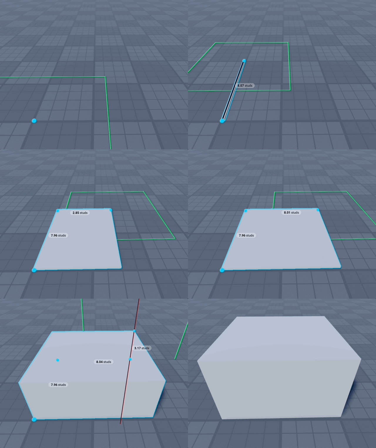
Center → Corner
Good when working with Grid, especially when creating many blocks and minimizing clicks.
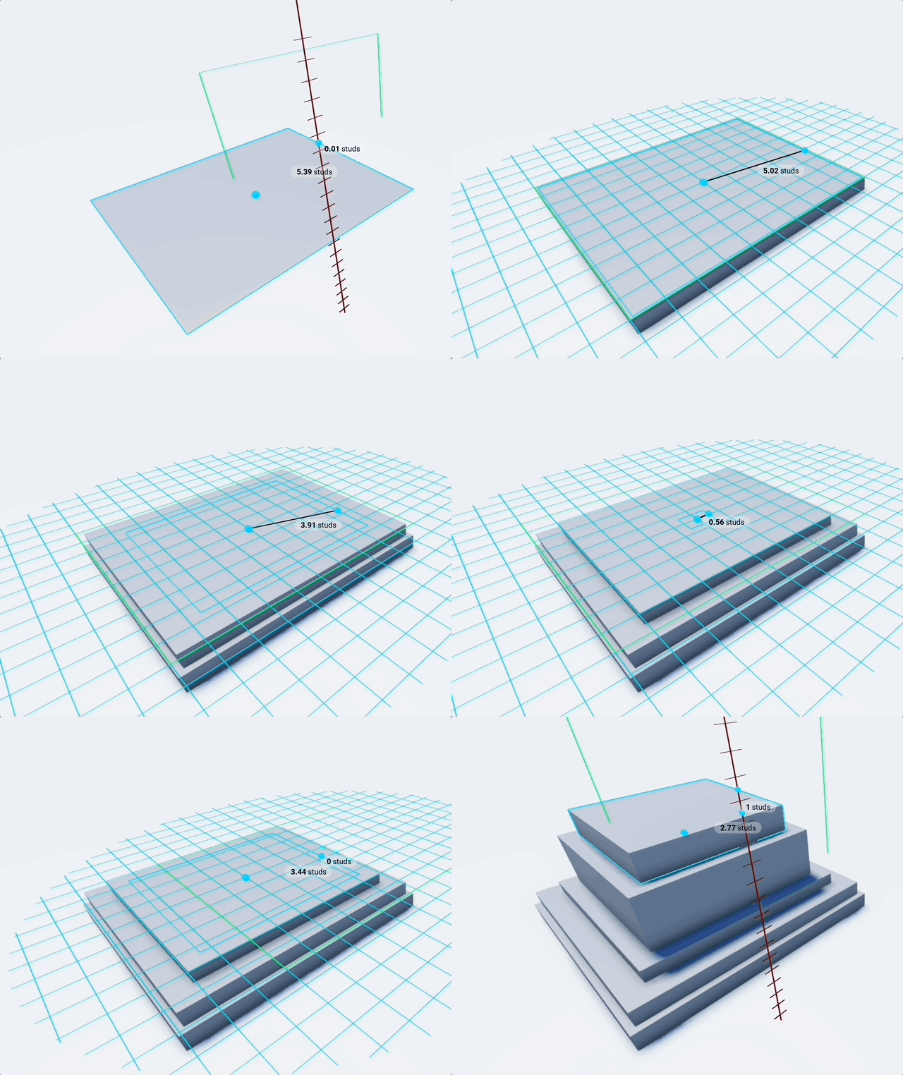
Square: Center → Side
Constrained square variant of the center-based mode. Click the center, then a side direction; width and depth are locked to be equal (square footprint). Great for fast, perfectly square floors/walls while staying aligned to the work plane and grid.
Preset Size (locked dimensions)
In Width → Depth → Height mode you can lock any of the three dimensions to a fixed value so you don't have to click to define it. This is great for repeatable footprints and for stamping parts at a constant height.

- Preset Size is a checkbox, so the dimension fields stay out of the way until you want them — and switching it off keeps whatever you had typed, it just stops applying.
- Width / Depth / Height: Type a value (studs) to lock that dimension. The corresponding click is skipped and the part is built using the preset value.
- Dynamic (0): Leave a field empty or set it to
0to keep drawing that dimension with the mouse as usual. - Saved presets: name the Width/Depth/Height you build with — Wall, Floor, Step — and apply it again with one click, from any place, any time. Delete the ones you've finished with; saving over a name replaces it.
- Tip: Lock just Height to drop many same-height blocks in one click each; lock Width and Depth for a fixed footprint you can place repeatedly.
Shape - Seat
Draws exactly like a Block, but the placed part is a real, working Seat (or VehicleSeat) — characters can sit on it in game with no extra setup. While you draw, a semi-transparent ghost character sits on the preview so you can size and position the seat against actual character proportions before committing.
Draw modes, preset sizes, and the rest of the panel match Block. Seat adds the settings below.
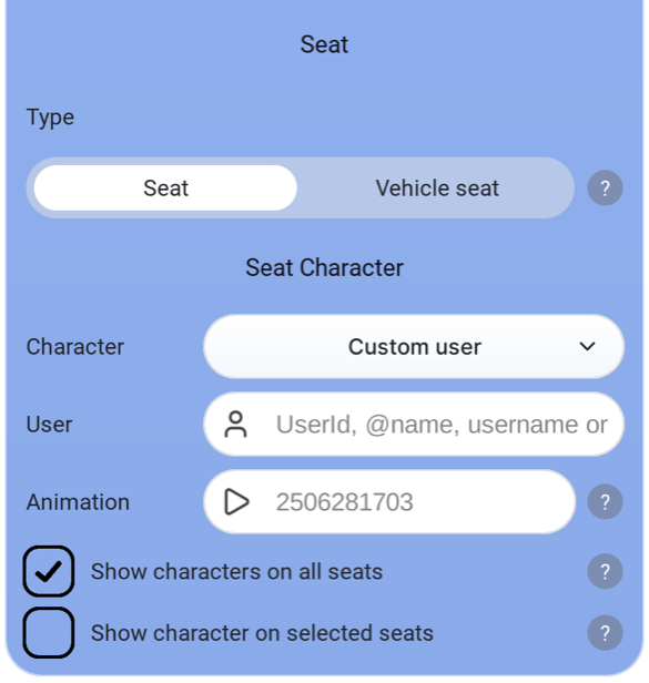
How to use
- Select the Seat shape from the shape selector (next to Block).
- Draw it like a Block — all Block draw modes and preset sizes apply.
- Watch the ghost character on the preview to judge seat height and depth, then click to commit.
The preview characters are never added to your game — only the seat part is placed.
Seat
Type
Which sit-part class is placed:
- Seat (default): characters sit when they touch it.
- Vehicle seat: a
VehicleSeat— also captures movement input from the seated player, so use it as the driver's seat of a vehicle.
Seat Character
Character
Who sits on the preview:
- R15 Noob (default), R6 Noob, Rthro Noob: standard rigs for checking classic proportions.
- My character: your own avatar.
- Custom user: any Roblox user — enter a UserId,
@name, username, or profile URL in the User field.
Animation
Animation asset ID the preview character plays while sitting. Leave empty for the default Roblox sit animation.
Show characters on all seats
While the Seat shape is active, also previews a sitting character on every Seat and VehicleSeat already in the workspace (occupied seats are skipped). Great for reviewing seat placement and spacing across a whole place at once. Preview only — the characters disappear when you switch shapes.
Show character on selected seats
Same preview, but only on seats currently selected in Studio.
Shape - Spawn
Draws exactly like a Block, but places a real, working SpawnLocation — a spawn pad players respawn on, with no extra setup.
Draw modes and preset sizes match Block. Spawn adds the settings below.
Spawn
- Neutral (on by default): anyone can spawn here whatever team they're on. Turn it off to reserve the pad for one team.
- Team colour (only shown when Neutral is off): which team spawns here. It must match that Team's
TeamColorexactly, or nobody will spawn on it. - Change team on touch: touching the pad moves the player onto its team. Handy for team-select rooms; leave it off for ordinary respawn points.
- Force field (s): seconds of spawn protection given to a player who spawns here.
0gives no force field.
Punch mode is not offered for Spawn. Cutting produces a UnionOperation, which is no longer a SpawnLocation.
Shape - Plane
Create a rectangular plane aligned to the current work plane. Useful for floors, walls, and reference surfaces.
Modes
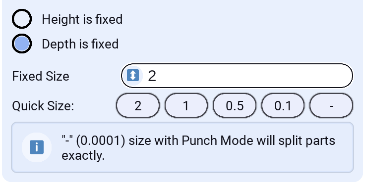
- Height is fixed: Locks height to a numeric value while you place width and depth. The fixed height is centered around the grid so adjustments feel intuitive as you move the mouse.
- Depth is fixed: Locks depth to a numeric value while you place width and height.
Settings
- Plane Mode: Choose Fixed Height or Fixed Depth
- Fixed Size: Numeric value for the fixed dimension (studs)
The Plane shape supports Punch mode to cut thin openings or surface slices out of other parts.
Set Fixed Size to "-"(0.0001) while using Punch Mode to split parts exactly along the plane (precise slicing).
Shape - Spiral Stairs
Treads winding around a central axis as they climb — tower staircases, lighthouse interiors, wizard towers.
Drawn centre → radius → height, the same three clicks as Lathe and Donut. Every setting describes one step — its turn, rise and thickness — and the staircase builds as many identical steps as fit the height you drag, so a tread never changes shape when the height does. You don't set a step count or a total turn: both fall out of the height.
Spiral Stairs Settings
- Turn per step (°): degrees each step turns around the centre.
36keeps ten steps to a full circle; smaller values make narrower treads and a tighter wind, negative winds the other way. The staircase's total turn is simply this times however many steps fit the height. - Rise per step: height gained per step. With the drawn height, this decides how many steps there are — a height that isn't a whole number of risers stops just short rather than fudging the last step.
- Tread thickness: how thick each step slab is. The top face is the walking surface — it sits exactly on the step height with the slab hanging beneath it — so matching the thickness to the rise stacks the treads into a solid column with no gap between them.
- Inner radius: size of the hole up the middle, as a fraction of the outer radius.
0runs the treads all the way to the centre; raise it to leave room for a central column. - Tread facets: segments per step.
1makes each tread a flat plank; more curves its outer edge to follow the circle, at one extra pair of parts each. A ramp wants 3–4 of these — they are what curve the deck as it turns. - Step gap (°): daylight between one tread and the next, trimmed off where each tread begins — the floating-steps look. The far end stays put on its step height, so the staircase still reaches exactly where you drew it. Negative stretches every tread's start backward instead, reaching it over the step below — the classic spiral stair, where every tread overhangs the nose of the one under it. An angle rather than studs, so it scales with the staircase; a gap bigger than a tread's whole slice of the turn leaves nothing to build.
- Step Y offset: extra studs each step climbs above the one below, on top of the rise — the first step stays on the surface you drew from, and the staircase still fills exactly the height you drag: bigger spacing simply means fewer steps, the last one landing on the height point. At
2with rise4, a step lands every 6 studs — jump-course spacing. Negative squashes the steps closer together and fits more in; going down, it deepens every drop the same way. - Continuous ramp: tilts every tread by exactly its own rise, so each one starts where the one below it ended — a smooth helical ramp instead of steps. Spiral car ramps, tower walkways, water slides. The pitch that joins the treads up depends on the radius, rise and turn, so it is computed per tread rather than set by hand.
- Tread tilt (°): leans each tread along the way you walk it.
0is a flat step, positive slopes it the way the staircase climbs, negative against — a couple of degrees of drainage fall, or a partial slope between steps and a ramp. Continuous ramp overrides it.
Each tread is an annular sector — a pie slice with the middle removed — rather than a box, so consecutive steps meet flush instead of gapping at the outer edge and overlapping at the inner one. Tilted and ramped treads are anchored at their walking surface and cut into concentric bands where the helix twists, so the deck stays seamless however steep it winds.
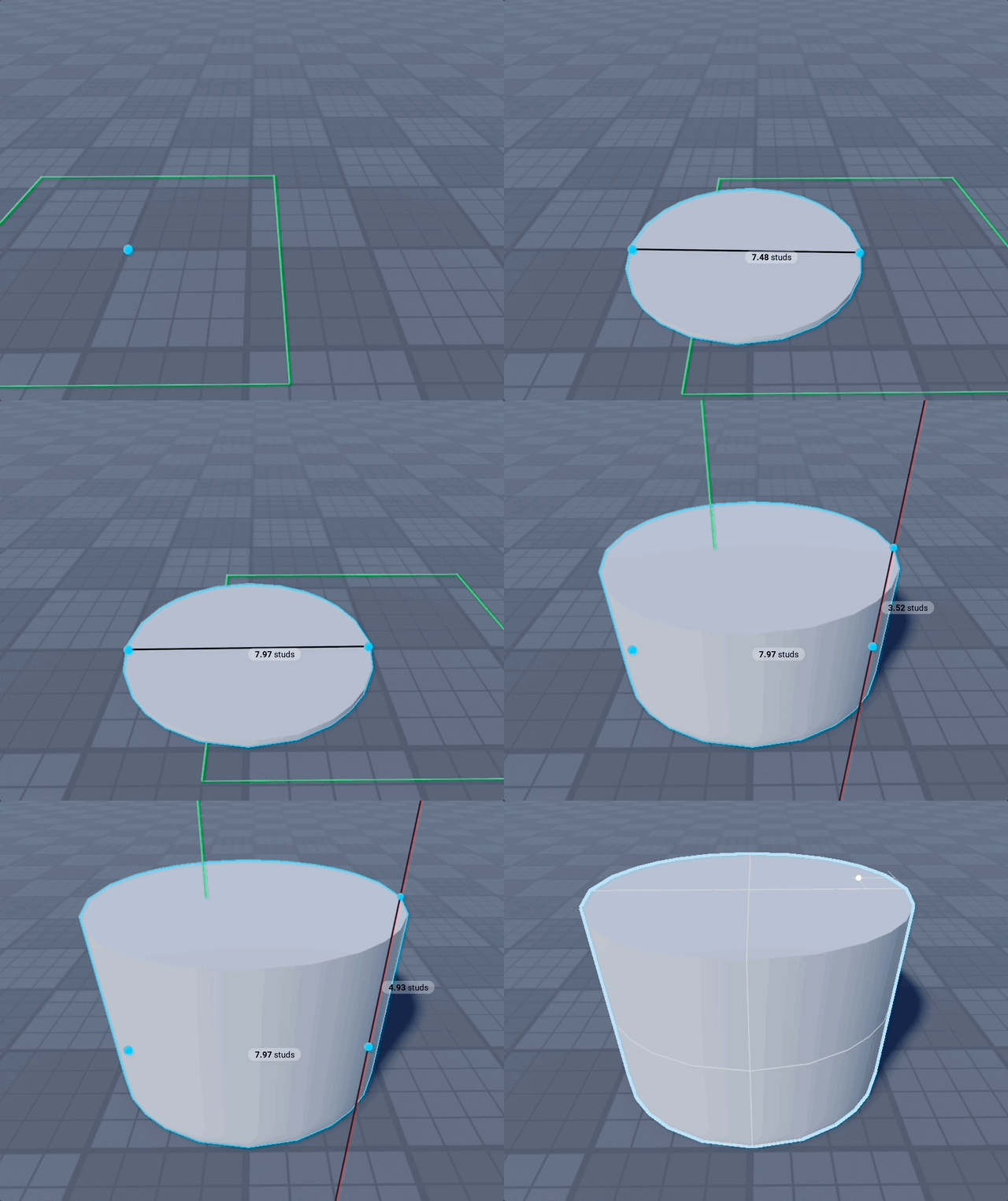
Shape - Cylinder
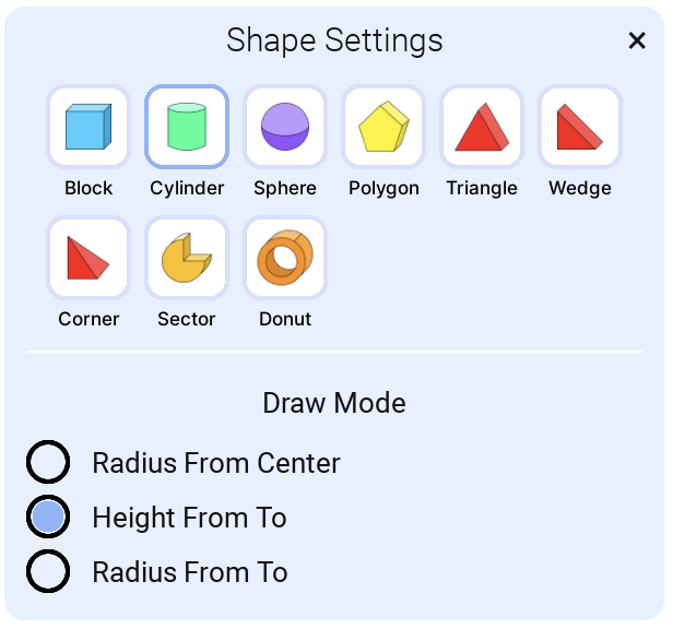
This creates a Roblox Part where the Shape property is Cylinder.
Draw Modes
You can choose from different draw modes to easily create cylinders for each scenario with accuracy.
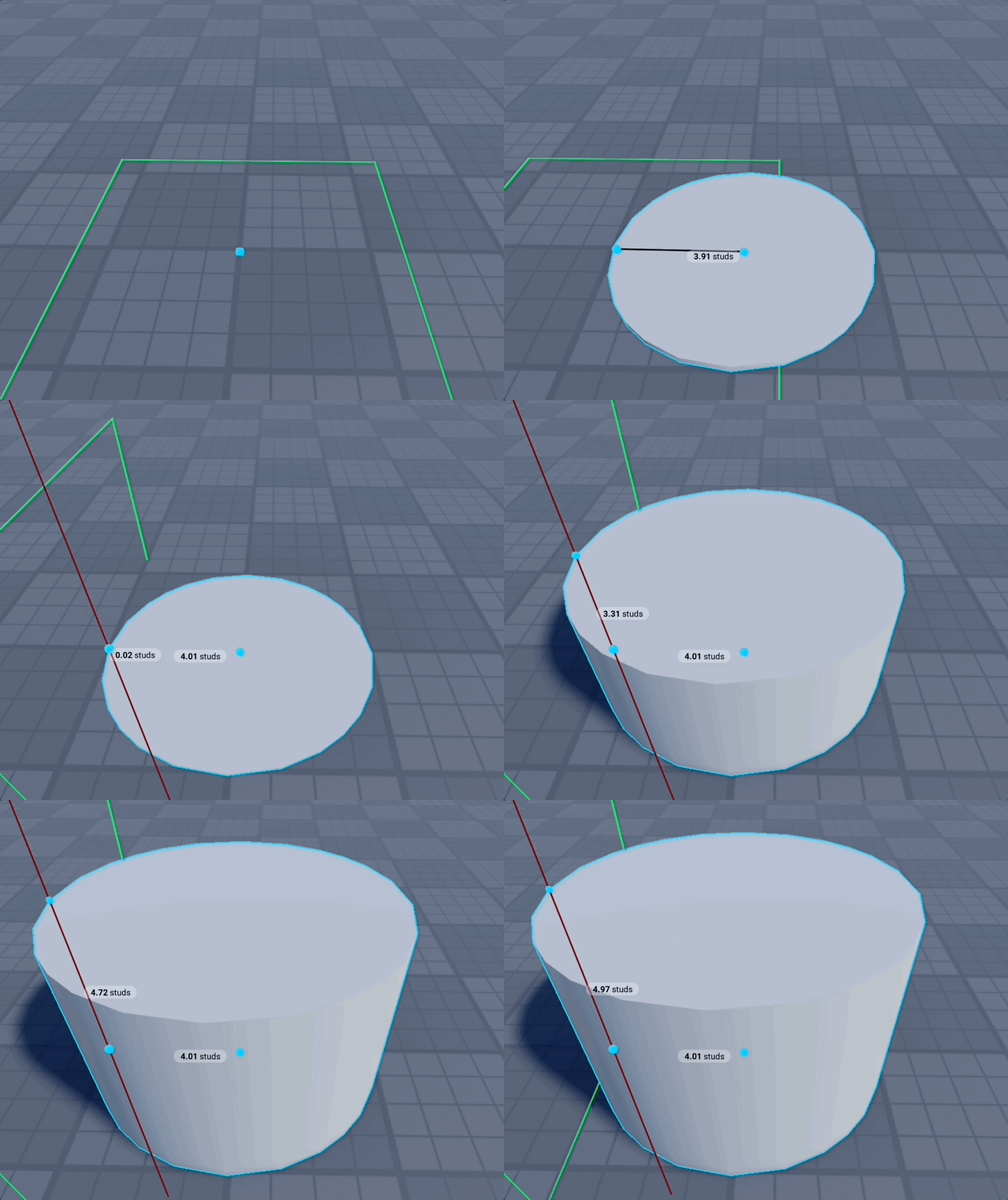
Radius From Center
When you know where you want the center of the cylinder to be.
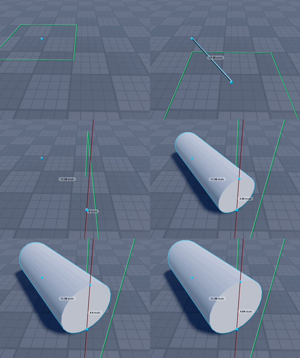
Height From To
When you want to create a cylinder on a surface, for example as a pipe.
Radius From To
When you want to create a cylinder so edges span from one point to another.
Shape - Sphere
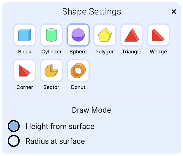
Draw Modes
You can choose from different draw modes to easily create spheres for each scenario with accuracy.
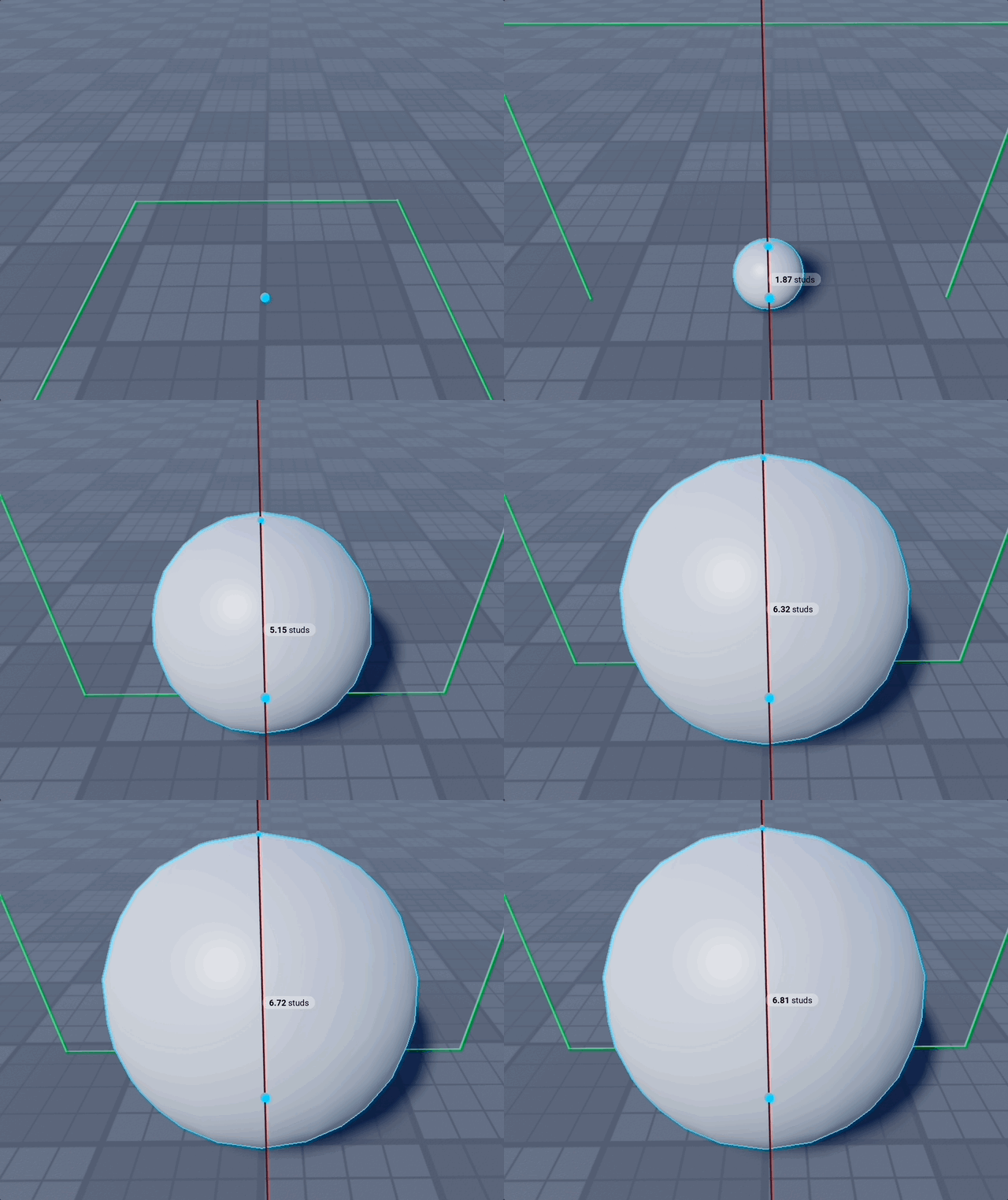
Height from surface
When you know how high you want the sphere to be in relation to other shapes in your build.
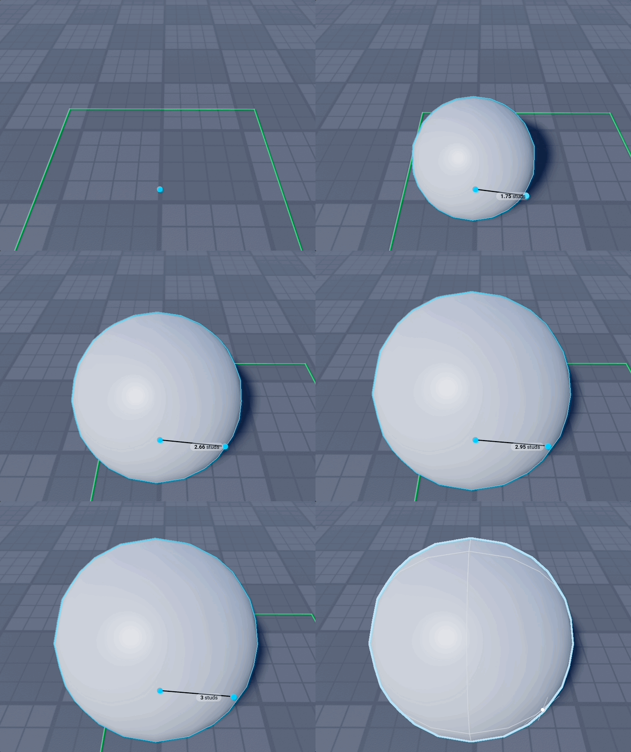
Radius at surface
When you know the width of the sphere. Especially good when working with Grid.
Shape - Lathe
A silhouette spun around an axis — the one shape behind every round, turned thing: cones, domes, bells, onion domes, barrels, pots, vases, jugs and wine glasses. Drawn centre → radius → height, and whichever profile you pick is scaled to the height you drag, so it squashes and stretches: a Perfect Dome as tall as its radius is a true half-sphere, shorter is a saucer, taller is an egg.
There is no separate Cone shape and no separate Dome shape, because they were never separate shapes — the same three clicks and the same machine, differing only in the curve handed to it. So the curve is a setting: Perfect Cone and Perfect Dome are the first two entries in the Profile list.
Lathe Settings
- Profile: the silhouette the shape is turned from — Perfect Cone, Perfect Dome, Onion, Bell, Vase, Jug and eleven more. This is the shape. See below.
- Steps: how many slices the profile is cut into, up its axis.
- Sides: how many flat faces it has around its axis. Only the faceted layers use it — the wedge rings and the corner wedges of the cap — so it greys out when Cylinder steps is the only layer on.
- Cylinder steps: builds each slice as an actual cylinder — a round surface with a stepped silhouette, whatever Sides says. One part per step, and the only layer that fills the shape solid.
- Smooth wedges: builds each slice as a ring of wedges instead — Sides flat faces with a sloped silhouette. See below.
- Pointed tip / Rounded cap (on a profile that closes to a point): closes the top instead of leaving a flat lid. The name follows the profile. See below.
- Cap steps (with the cap on, on a curved profile): how many steps the cap itself is cut into. See below.
- Top radius (with the cap off): how wide the flat top is, as a fraction of the base circle. See below.
- Step Offsets (Advanced): step each slice out or in, and give it a straight vertical face, so the shape reads as built courses rather than a turned surface. See below.
Roblox has no cone part and no hemisphere part, so a Lathe is built as a stack of cylinder discs following the profile. That means a slightly stepped silhouette — raise Steps if you need it smoother, lower it if you care more about the part count.
Profiles
Profile is the silhouette that gets spun, like a potter's template held against the clay. Everything else in the panel is how finely it gets built.
The list is in two halves. The first close to a point, so they can be finished off with a tip or a crown:
| Profile | Silhouette | Good for |
|---|---|---|
| Perfect Cone | a plain straight taper to a point | cones, spires, hip roofs |
| Perfect Dome | a quarter circle | domes, saucers, onion-tall domes |
| Bullet | holds its width, then noses over | silos, rockets, round towers |
| Egg | a dome with its widest point above the base | eggs, seeds, huts, water towers |
| Bell | pulls in fast, then runs up into a neck | bells, vases, chess pieces |
| Onion | swells above the base, then closes to a point | onion domes, finials, gourds |
| Cove | concave taper | flared roofs, pagoda tiers, trumpet mouths |
| Wavy | a taper with ripples running up it | turned finials, coral, screws, cartoon trees |
| Mushroom | a stalk under a cap half again as wide | toadstools, parasols, sun umbrellas |
The second half end on a real radius, so they keep a flat top — the tip/cap option does not appear for them, since there is nothing to converge to:
| Profile | Silhouette | Good for |
|---|---|---|
| Barrel | bulges through the middle and comes back | casks, tanks, boilers, pumpkins |
| Tapered | a cone cut off half way | pots, plinths, kegs |
| Cup | opens gently out to a wider rim | tumblers, plant pots, bins, lampshades |
| Vase | belly, waist, and a rim that opens back out | the everyday flower vase |
| Urn | a deep belly drawn into a tight neck under a flared lip | amphorae, trophies, planters |
| Jug | full body, hard shoulder, narrow neck | bottles, jars, flasks, decanters |
| Goblet | a foot, a thin stem, and a cup opening back out | chalices, wine glasses, fonts |
| Hourglass | pinched to a third of its width and back out | egg timers, spools, column capitals |
Picking a profile that closes also switches its cap on for you, which is what makes Perfect Cone and Perfect Dome come out perfect from a single click. Picking one that ends flat switches it off, since it could not use it.
Every profile is exactly as wide as the circle you dragged at the base, so whatever you pick sits on its footing the same way. Profiles that bulge — Onion, Barrel, Vase, Mushroom — swell wider than that circle further up: the drawn radius is where the shape meets what it stands on, not a bounding box.
Profiles that widen as they rise are built with their ramps hanging from the ceiling of each slice instead of standing on its floor — the same notch entered from underneath. Nothing about the settings changes; it is worth knowing only because it is what makes an onion dome's shoulder, a goblet's cup or a flared eave possible at all.
A profile with detail packed into it — Wavy, Jug, Goblet, Mushroom — needs enough Steps to catch that detail. A coarse stack samples straight past a ripple or a neck and gives you back a plain taper.
How the slices are spaced
Steps are spread around the curve, not down the height: a dome's slices are thin at the crown and thick down the sides, so each one covers the same amount of shape.
This matters most on a saucer. Cut a flat-ish dome into equal slices of height and the top slice has to cross a third of the radius on its own — an enormous step right where you are looking at it, with a wide flat lid on top — while the bottom slices cross almost nothing and are invisible. Spacing by curve puts the detail where the shape actually turns.
A Perfect Cone's profile is a straight line, so there is nothing to redistribute and its slices come out evenly spaced either way.
Pointed tip / Rounded cap
A stack of cylinders always ends in a cylinder, so a shape built from discs alone is left with a flat disc on top. This checkbox takes the topmost slice over — no disc, no ramp — and builds a converging cap there instead, from a pair of corner wedges per facet. It replaces that slice rather than adding to it, so the shape still ends exactly at the height you dragged.
How it reads is the profile's business, which is why the checkbox is named after it. Because the slices follow the curve, a cone's top slice is tall and narrow and comes to a sharp point; a dome's is short and wide and rounds over into a crown. Same construction, both ways.
It costs Sides × 2 parts, and it is switched on for you whenever you pick a profile that closes.
Set Steps to 1 with the tip on, on Perfect Cone, and the tip is the whole shape — a clean Sides-sided cone from Sides × 2 parts and nothing else. That is the cheapest way to a pyramid-like cone: 4 sides for a square-based one, 6 for a hexagonal one. Raise Sides rather than Steps to smooth it out.
Cap steps
A slice is sized for the flank, and on a tall dome the flank and the crown are nothing alike: one slice of curve down the side is a gentle slope, the same slice at the pole is where the whole radius collapses. Run a single straight cap across that and the dome ends in a spike, no matter how high you push Steps.
Cap steps cuts the cap into slices of its own, spaced around the curve exactly like the rest of the shape, with only the last one converging to the point. Three or four is enough to turn a spike back into a crown, and it is far cheaper than raising Steps — which would refine the whole dome to fix one slice at the top. It defaults to 3, and costs one part per extra slice with Cylinder steps, or a ring each with Smooth wedges.
It applies to any curved profile. A straight taper does not need it and does not get it: subdividing a straight line gives back exactly the same straight line.
Cylinder steps and Smooth wedges
These are the two ways a slice can be built, and they are independent — either one, or both together. You cannot switch both off; unchecking the last one switches the other on instead, since there would be nothing left to build.
Between two slices there is a notch: the ledge where the wider one ends, and the side of the narrower one above it. Smooth wedges fills that notch with a ring of wedges, so the outline ramps from one slice to the next instead of stepping. The bottom slice gets a ring too, ramping down to meet the ground at exactly the radius you dragged — without it the shape stands on a stubby cylinder half a step narrower than the circle you drew.
Each ring is wedges, each extended sideways by a corner wedge on either flank so its ramp carries on past its own width. Without them the wedges meet only where their tall edges touch the slice above, leaving a V-shaped notch at every seam.
Smoothing is off by default because it is not free: a plain stack is one part per step, a smoothed one adds about steps × Sides × 3 on top. The panel shows a running part estimate and warns when it gets large — prefer raising Steps first, and reach for smoothing when you want a clean slope at a modest step count.
Every ring spans exactly one slice of the shape you drew, edge to edge, so the chain of them traces your silhouette from the ground to the top with no kink at either end. With smoothing on the cylinders change job: they stop being the surface and become the core, sized to sit just inside the flat faces so no round rim pokes back out through them. That is why turning smoothing on makes the discs a touch narrower — they are hiding.
Each ring is a polygon inside a round profile — that polygon is what Sides counts. Midway between two faces the surface sits slightly under the true curve, a shallow dip that more sides remove: at 6 the shape is frankly faceted, at 12 the dip is faintly visible on a cone, at 24 it is essentially gone. The corners always land exactly on the circle you dragged, so nothing ever reaches past it.
A cone benefits from smoothing most, since its silhouette is a straight slope that steps very visibly at low step counts — and with the wedges on, Sides is the difference between a hexagonal cone and a round one.
With Cylinder steps off, the wedges build a shell: the outside is exactly right and it is the cleanest-looking option, but there is nothing inside it. Leave the cylinders on if the shape has to be solid — as a Punch mode cutter, for instance, where a shell would carve a shell.
Top radius
With the cap off, the shape ends on a flat face — and Top radius is what decides how wide that face is, instead of leaving it wherever the last slice happened to land. It is a fraction of the base circle you dragged: 0.5 cuts the shape off where it is half as wide as its base, 0 leaves it running all the way to its own end (a point, for most profiles). That is the default, so nothing changes until you ask it to.
The shape still reaches the height you drew: what is left below the cut is stretched to fill it. So this changes the taper, not the size — a Perfect Cone at 0.5 is a truncated cone, a Perfect Dome is a dome with its crown taken off and the rest stretched back up. Chimneys, silos, plinths, wells, water towers, cooling towers, drums.
Two things worth knowing:
- The field only appears with the tip or cap off. The cut and the cap are two answers to the same question — what happens at the top — so only one of them is ever live.
- A profile that never gets that narrow has nothing to cut, and keeps its own top: a Barrel is never narrower than its base, and a Tapered cone stops at half. The panel says so rather than leaving a field that quietly does nothing.
With Cylinder steps on, that flat top is a solid lid. With Smooth wedges alone the shape is a shell, so the flat top is an opening — which is exactly what you want for a well or a chimney, and worth remembering if you wanted a lid.
Step Offsets (Advanced)
Everything above works to hide the seam between slices: each ring hands its top edge straight to the next, so the shape reads as one turned surface. Step Offsets breaks that seam on purpose, by a number of studs you choose, so the same dome can be built as courses of stone instead of thrown on a wheel. Both settings are 0 by default, both are measured in studs, and both need Smooth wedges on — a stack of cylinders has no seam between slices to offset.
- Step ledge is horizontal: how far each slice jumps out from (or into) the one below it, instead of continuing off it. Positive juts every course past the one under it, leaving a shelf facing down all the way round — corbels, eaves, pagoda tiers, cornices. Negative sets every course back inside the one below, so the shelf faces up and the shape climbs like a stepped drum or a ziggurat.
- Step riser is vertical: how much straight wall each slice starts with before it begins to slope — the riser to the ledge's tread. Positive holds the slice's own width, giving a flat face under every ledge, the way a stone course reads. Negative holds the width the slice ends on instead, so each course starts undercut and flares back out — a recessed groove at every junction, with the course above sitting proud of it.
The bottom slice never moves, so the footprint stays exactly the circle you dragged, and the offset does not stack up the shape: every slice still ends on the profile, so the silhouette keeps following the curve however many courses it is cut into.
A riser taller than a slice simply takes the whole slice, turning that course into a plain cylinder wall — a legitimate shape (a stack of drums), so it builds rather than complaining. Each riser costs one part per side per step, on top of the wedges.
Small numbers do the most work here: on a 20-stud dome at 8 steps, a ledge of 0.5 and a riser of 0.5 is already unmistakably built rather than turned.
Shape - Polygon
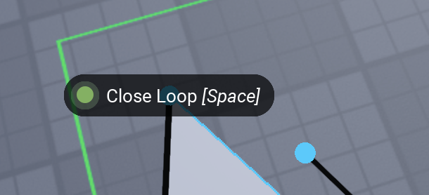
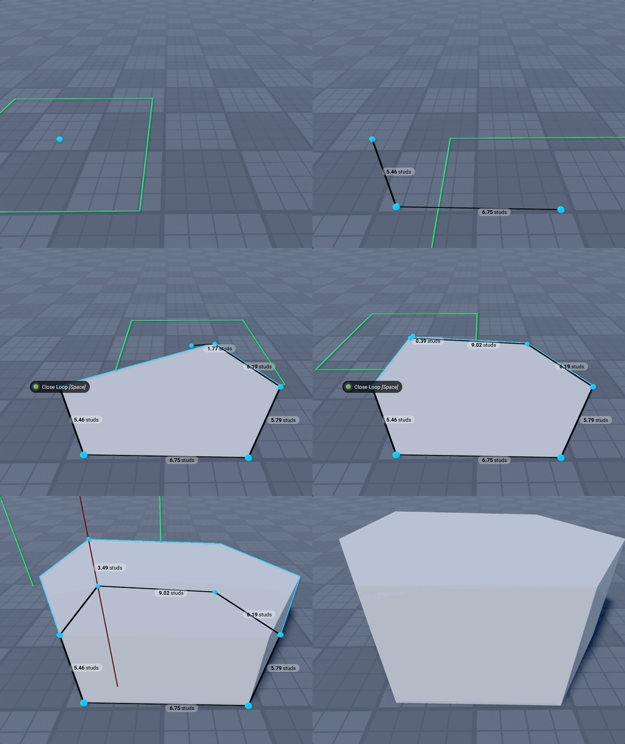
Set as many points for your polygon as you like. You can undo or go to "Edit Mode" if you misplaced your point. To finish building go near first point and click the "Close loop" button (Or press Space any time to close loop). Your last and first point will be connected perfectly. And then you can define the height. And after that you have created a polygon shape.
Outline Mode
Polygon can also generate its outline for you instead of having you click every corner.
- Freehand (default): the click-each-corner flow described above.
- Regular: click a centre, drag to size, and get an even-sided polygon — hexagon floors, octagonal towers. Sides sets the count.
- Star: the same two-click placement, with alternating points and valleys. Points sets the tip count and Inner radius how far the valleys sit in (lower is spikier).
Regular and Star hand over to the usual height click once placed, and the generated points stay fully editable in Edit Mode — so they're a starting outline, not a locked shape. Every triangulation algorithm, GRID mode and Punch mode works on them exactly as on a freehand polygon.
Triangulation Algorithm
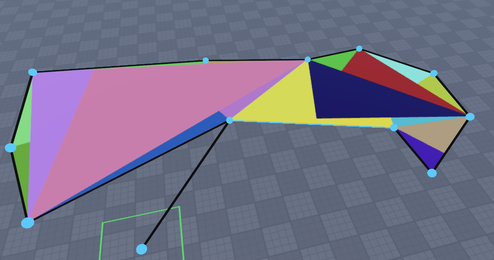
You can set different triangulation algorithms. The default is fine in most cases. If a polygon is not drawn correctly, try changing the algorithm:
- Ear-clipping (Default)
- Delaunay (Better Triangles - does not create long and narrow wedges)
- Simple (Non‑concave — not needed in most cases; does not work with concave polygons)
- Grid Based (Experimental)
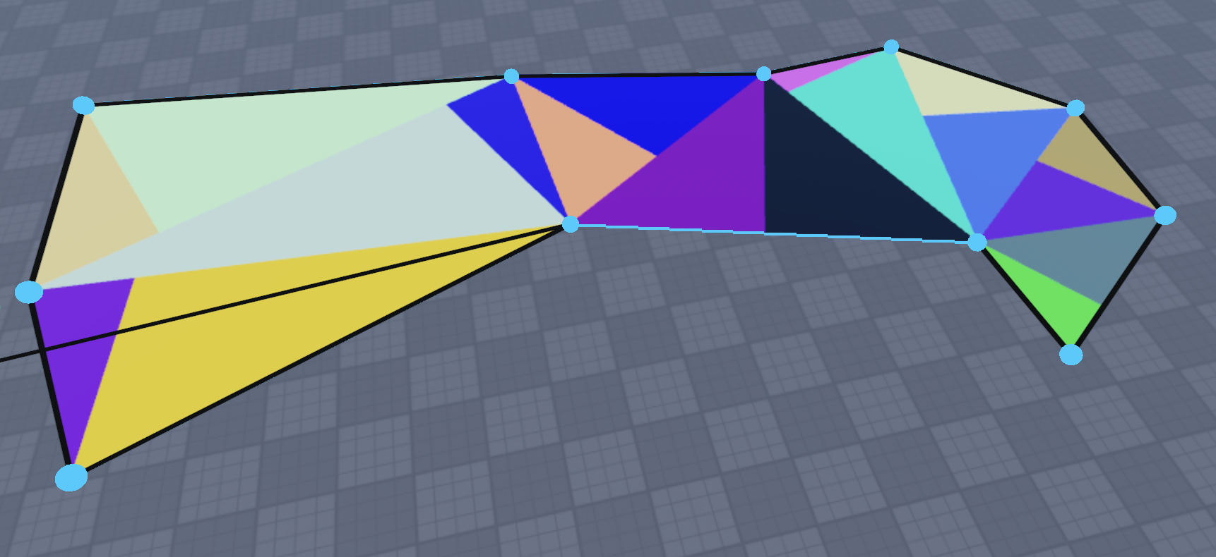
When the "Visualize part" setting is enabled, you can see the difference in wedge generation:
-
Ear-clipping
-
Delaunay
-
Simple
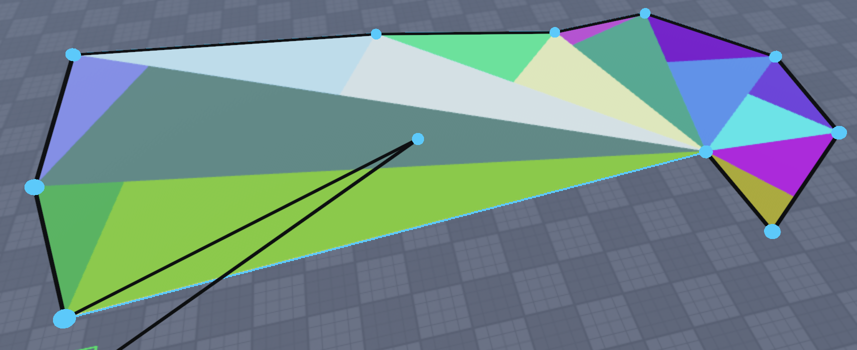
Demo of using Triangulation Algorithm and Visualize part settings
Edit Mode
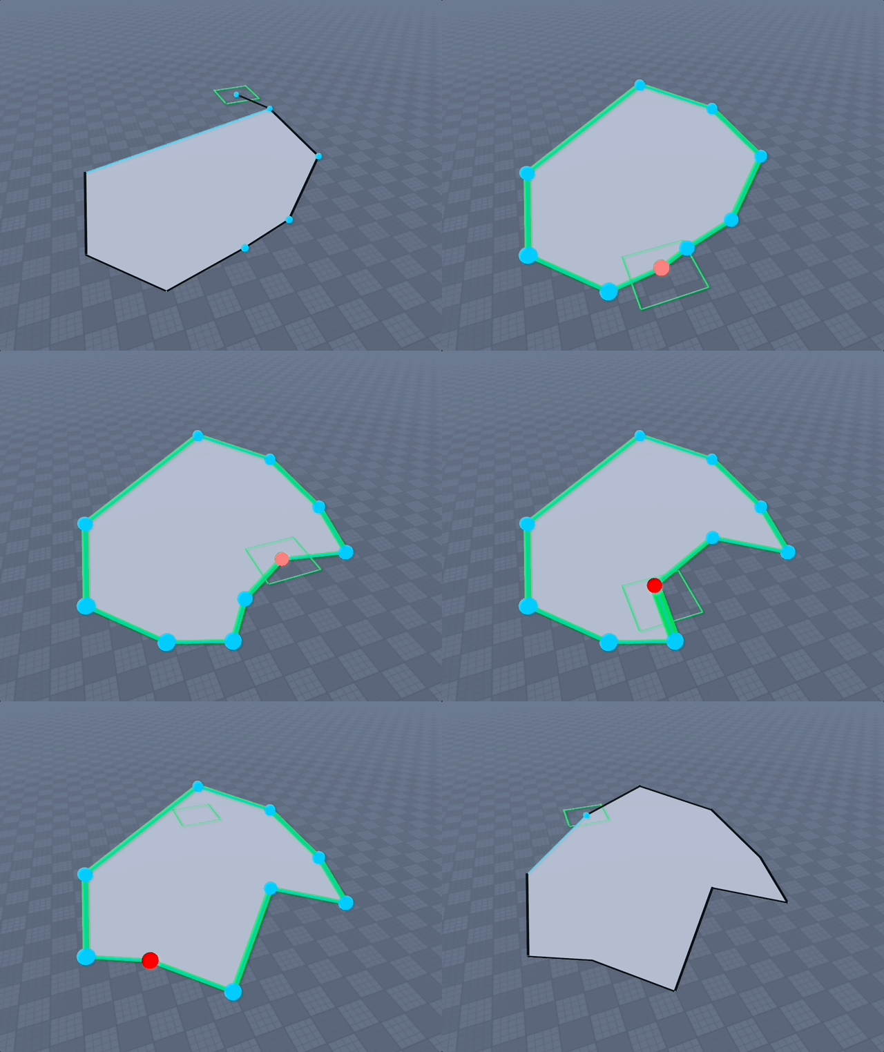
When you enable "Edit Mode" for a polygon, you can remove, move, and add points:
-
Remove point: Click a point; when selected it turns red and you can press Backspace/Delete to remove it.
-
Add point: Click an edge to create a point, then click & drag the point. Or click & drag directly on the edge to create and move a point immediately.
-
Move point: Click & drag a point to move it; release when done.
Edit selected polygon
You can edit an already created polygon. It does not have to be created with this plugin. It can even be a plain Part.
Select all the parts that make up a polygon, or a folder/model that contains those parts as children.
Then press "Edit Selected Polygon ✏️". It regenerates all corner points including the height point and goes into Edit Mode. Then you can change height or move/remove/add points. When done, either:
- Exit "Edit Mode" by unchecking Edit Mode checkbox (or using shortcut Shift+G)
- Click "Finish Building" (or using shortcut Shift+T)
Note: Separate the UnionOperation before editing; otherwise you’ll be editing its bounding box.
Boundary polygon from selection
Good if you want to connect two shapes that are not connected. Select any number of parts, click "Boundary Polygon from Selection ➕", and a polygon with boundary points around your selection is created. Define height and you are done.
Exact polygon from selection
This functionality is a predecessor to "Edit Selected Polygon". It creates a copy of the selected polygon and lets you define the height. Of course, you can go into Edit Mode yourself. This might be removed at some point, or become an "Edit Selected Polygon" that copies instead of editing. The idea is you could do low‑poly mountains by creating a base polygon, then copying and editing the height and some points to gradually go higher.
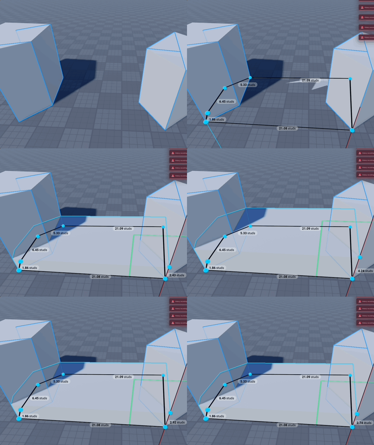
Demo of going into edit mode while creating a polygon
Demo of Editing a Polygon from selection
Demo of creating Polygon from selection
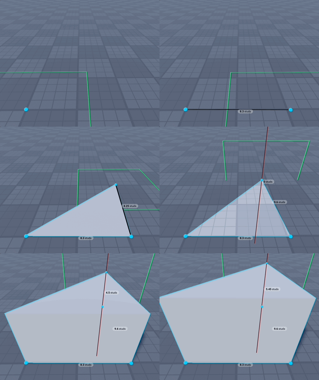
Shape - Triangle
Shape - Wedge
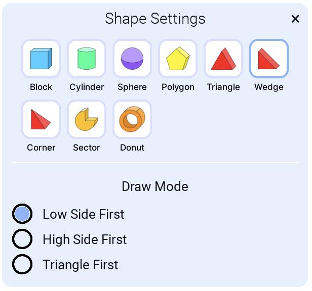
Draw Mode
Low Side First
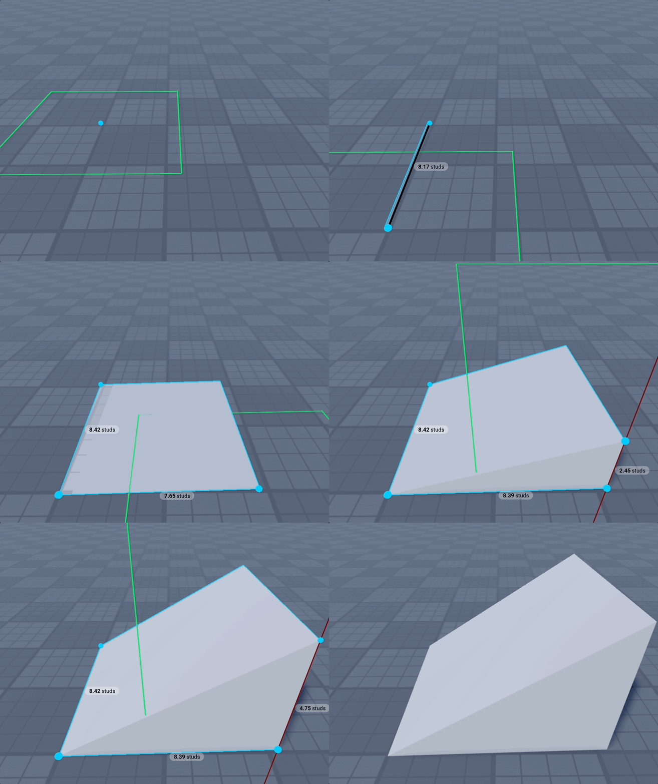
High Side First
Use High Side First when you want to add a wedge against a part and can snap to part corners for perfect alignment.
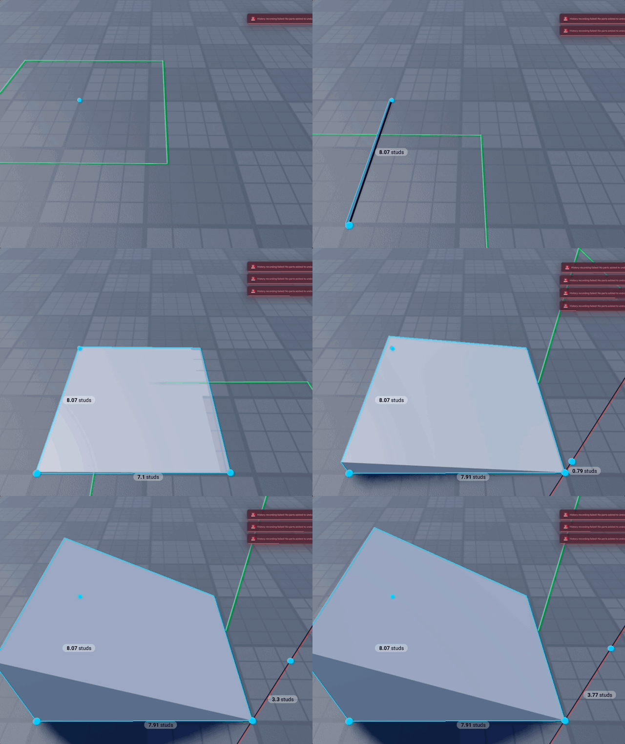
Triangle First
If you need a wedge on its side.
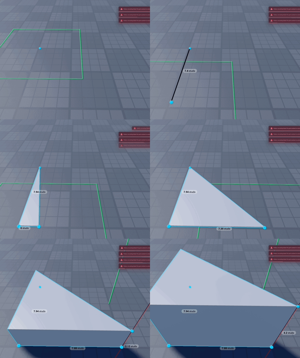
Shape - Corner
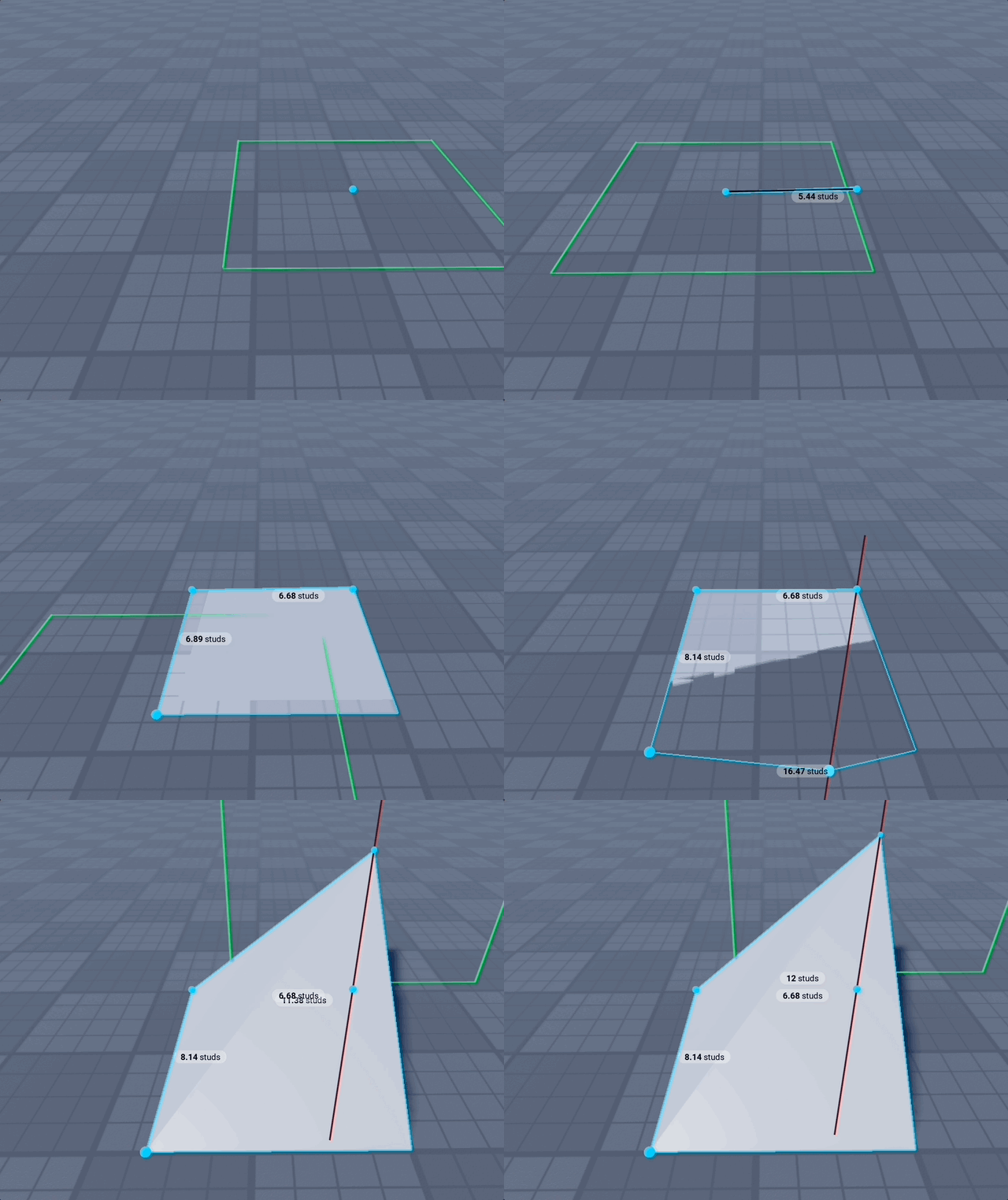
Shape - Pyramid
Build a pyramid made of four CornerWedge parts that meet at a shared apex.
Draw Modes
- Width → Depth → Height
- Center → Corner
- Square: Center → Side
Shape - Platform
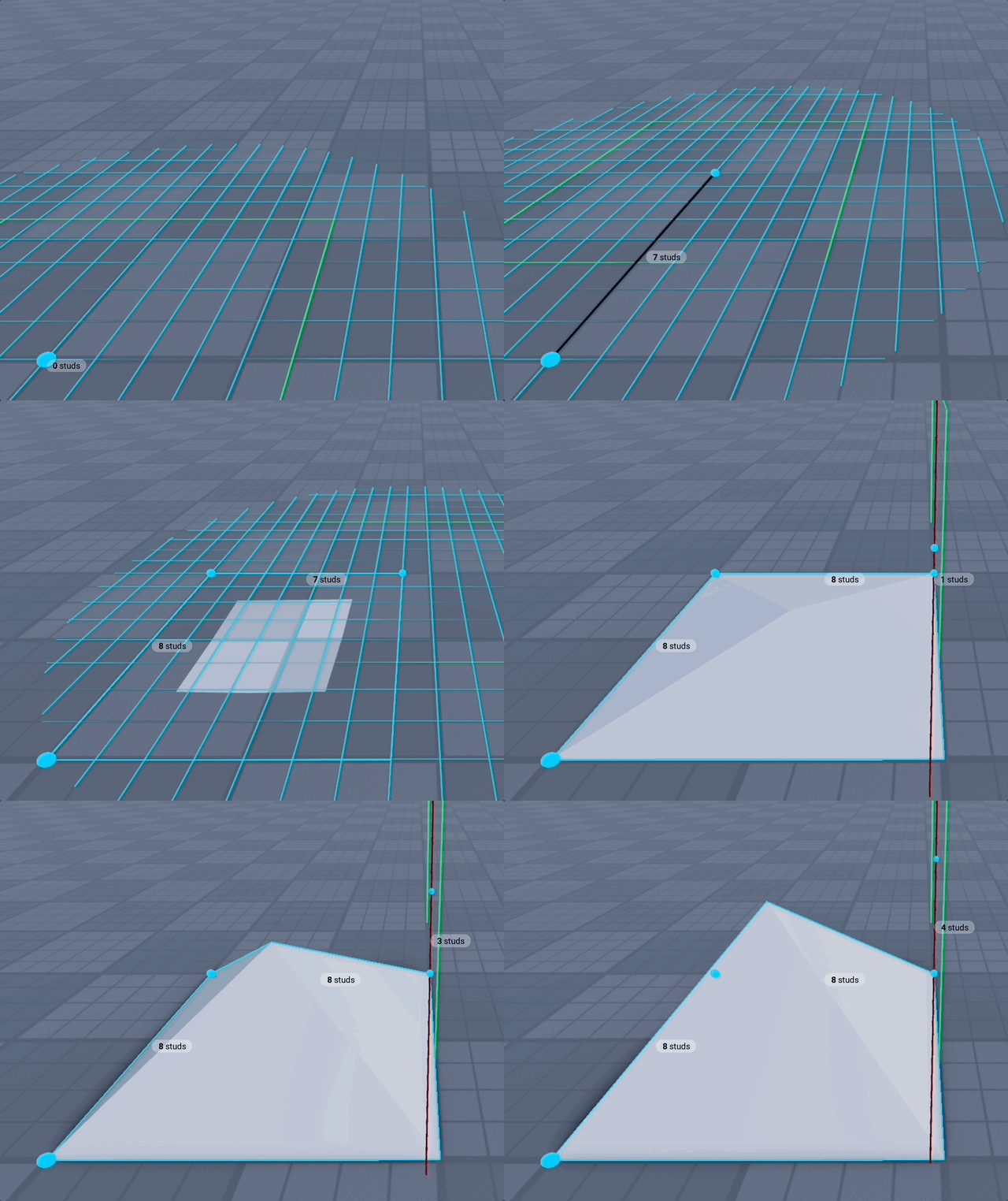
Create frustum of a pyramid, in simple terms - a platform.
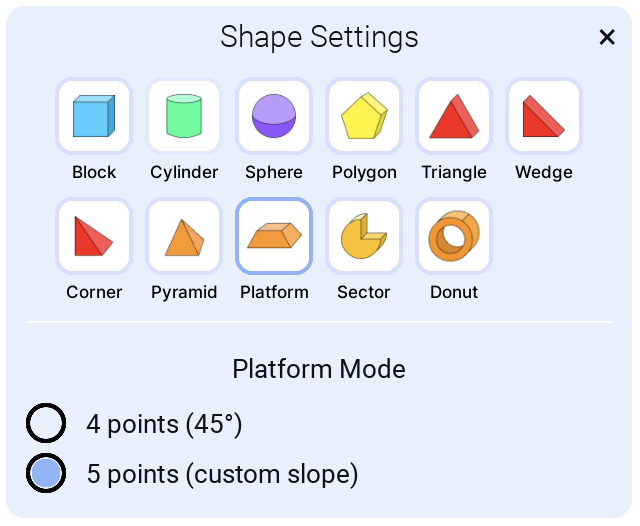
4 points (45°)
Predefined slope, for quick platform
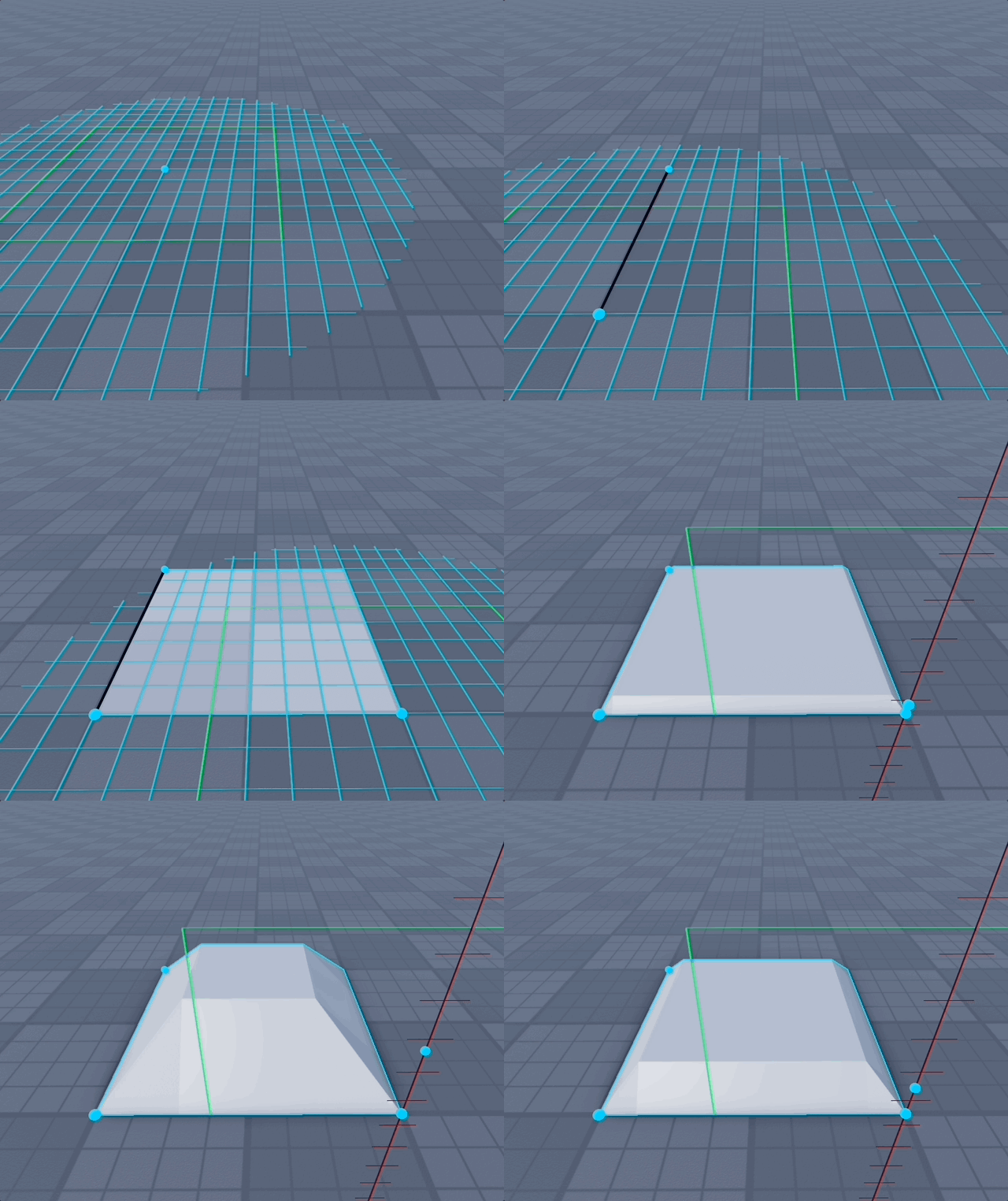
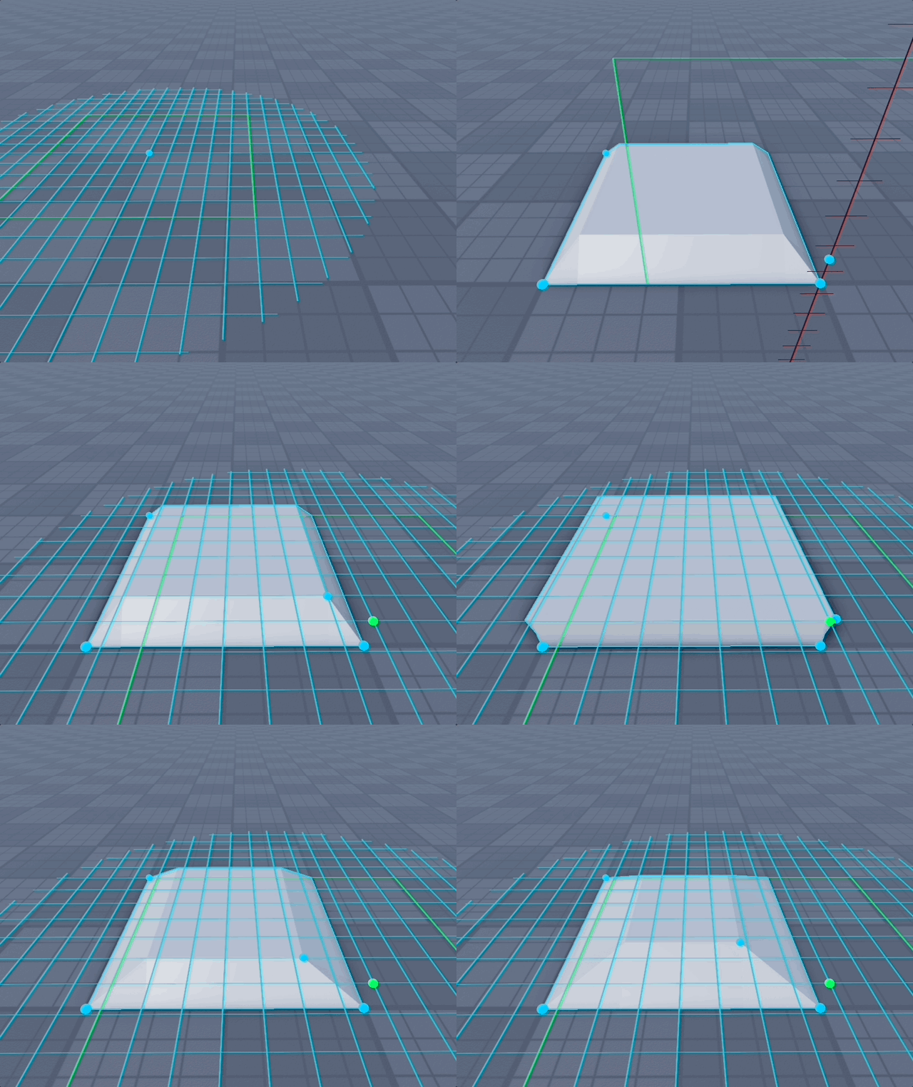
5 points (custom slope)
For last point you will defined slope, it can be inwards or outwards. So you can create upside down platform.
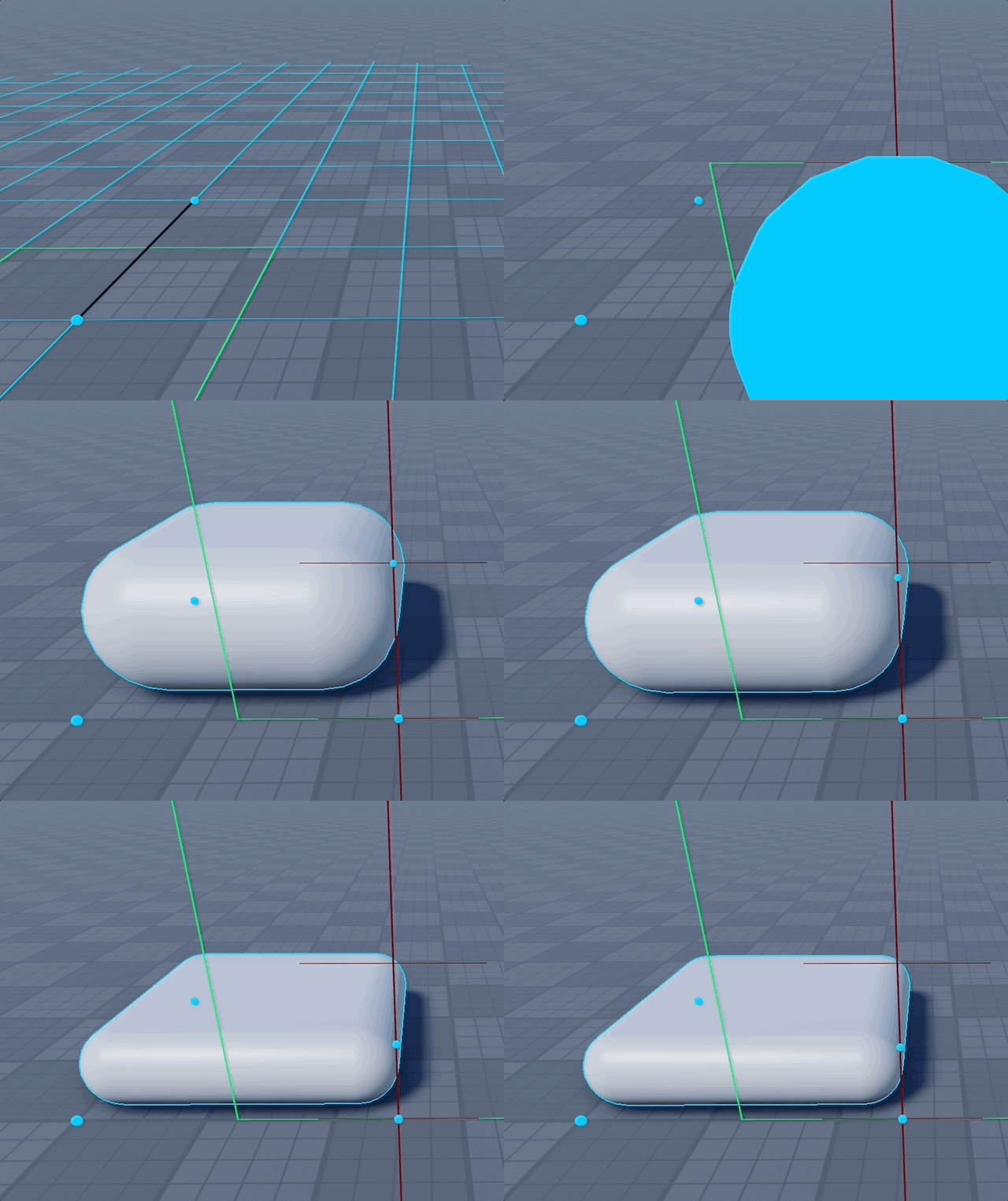
Shape - Pill
Create a rounded capsule-like block.
Draw Modes
- Width → Depth → Height
- Center → Corner
- Square: Center → Side
Shape - Roundbox
Create a fully rounded rectangular block (rounded edges and corners). Great for soft, polished shapes and filleted blocks.
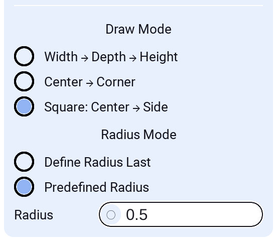
Draw Modes
- Width → Depth → Height
- Center → Corner
- Square: Center → Side
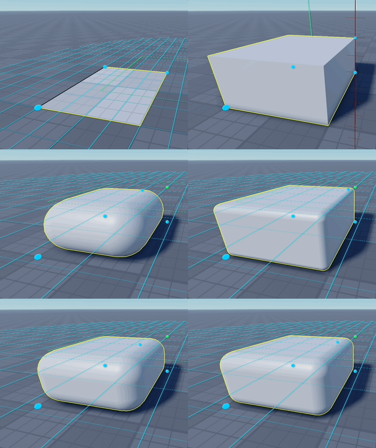
Radius Modes
- Define Radius Last: after setting width/depth/height, place one extra point on the top face to set the inner flat size; the radius is derived from that, letting you visually dial in the corner roundness.
- Predefined Radius: type a numeric radius that is used directly (default 0.5). Radius is clamped so it never exceeds half of width/depth/height.
Works with Punch mode to cut rounded openings.
Shape - Quadbox
A performance-friendly rounded rectangle variant. Produces straight top/bottom faces with rounded vertical corners (no corner spheres or top/bottom edge cylinders), ideal when you want rounded sides at lower part counts.
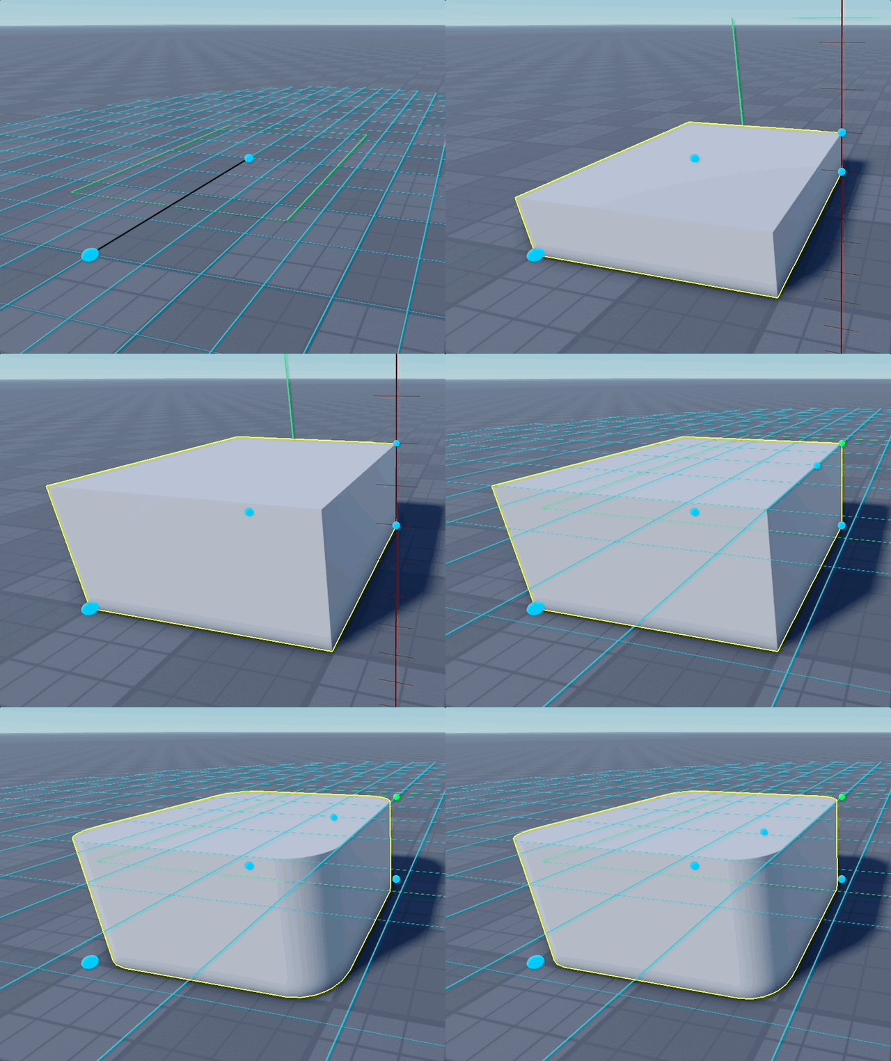
Draw Modes
- Width → Depth → Height
- Center → Corner
- Square: Center → Side
Radius Modes
- Define Radius Last: after setting width/depth/height, place one extra point on the top face to set the inner flat size; the radius is derived from that, letting you visually dial in the corner roundness.
- Predefined Radius: type a numeric radius that is used directly (default 0.5). Radius is clamped so it never exceeds half of width/depth/height.
Shape - Sector
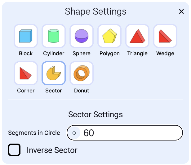
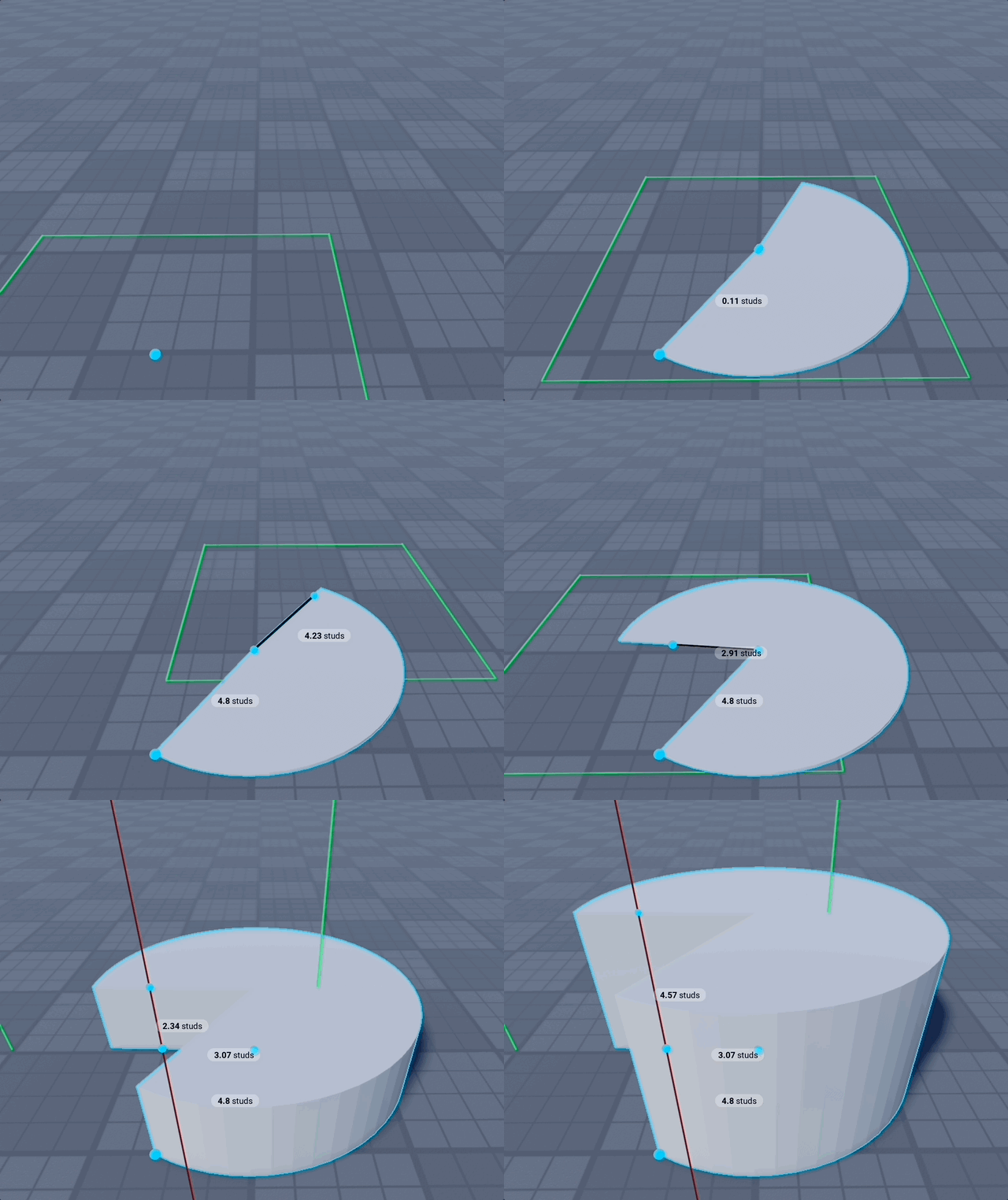
Segments in circle
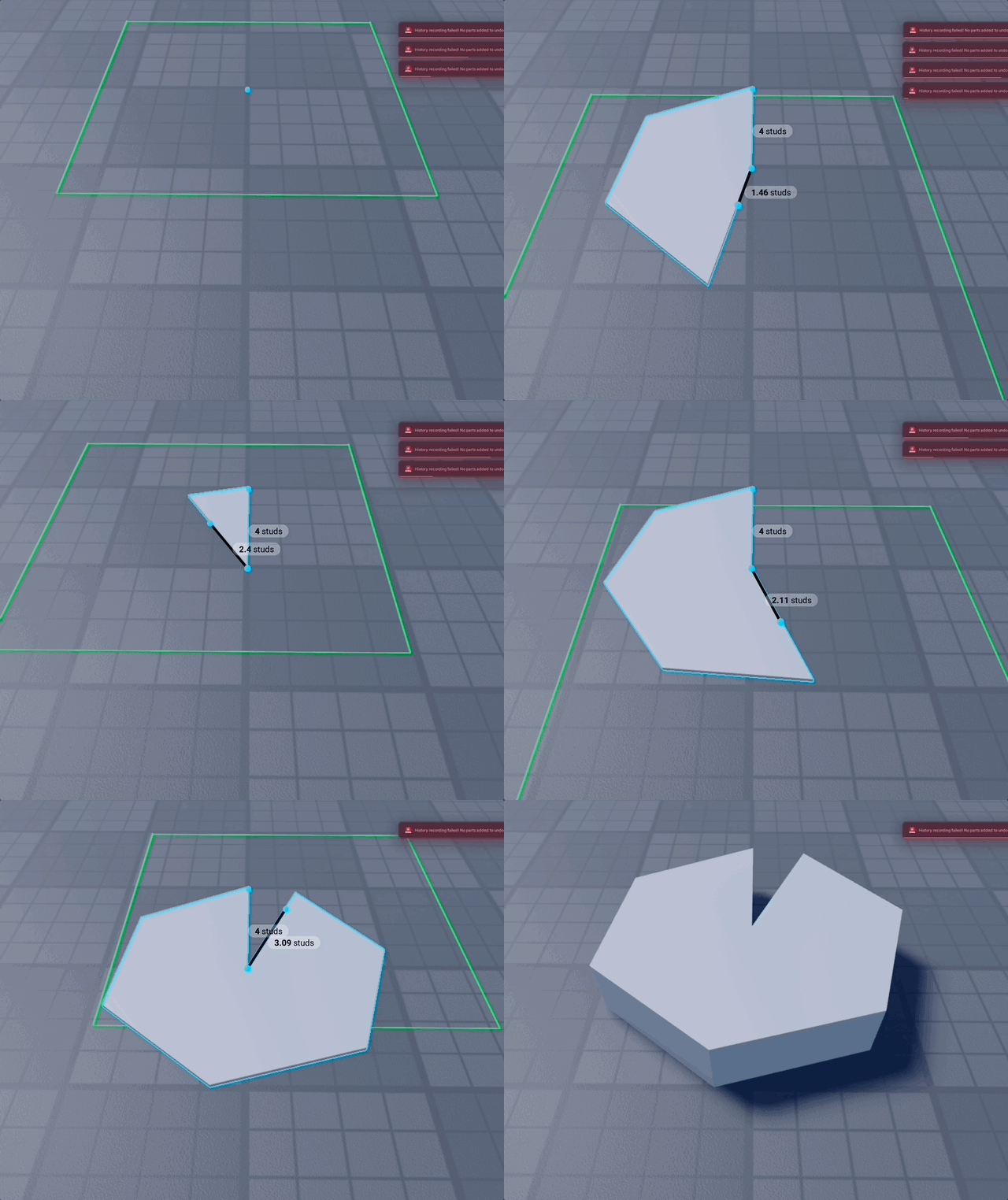
This is the segment count for a full circle. For a quarter sector, it uses one quarter of the segments. For example, with 60 segments, a 90° sector uses 15. Default is 60. Here is one with 6 segments:
Inverse Sector
Change the direction of sector cutting: left vs right.
Shape - Donut
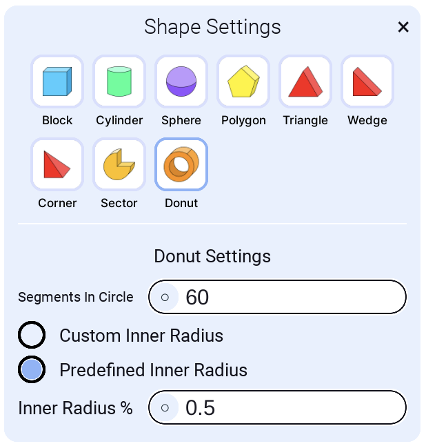
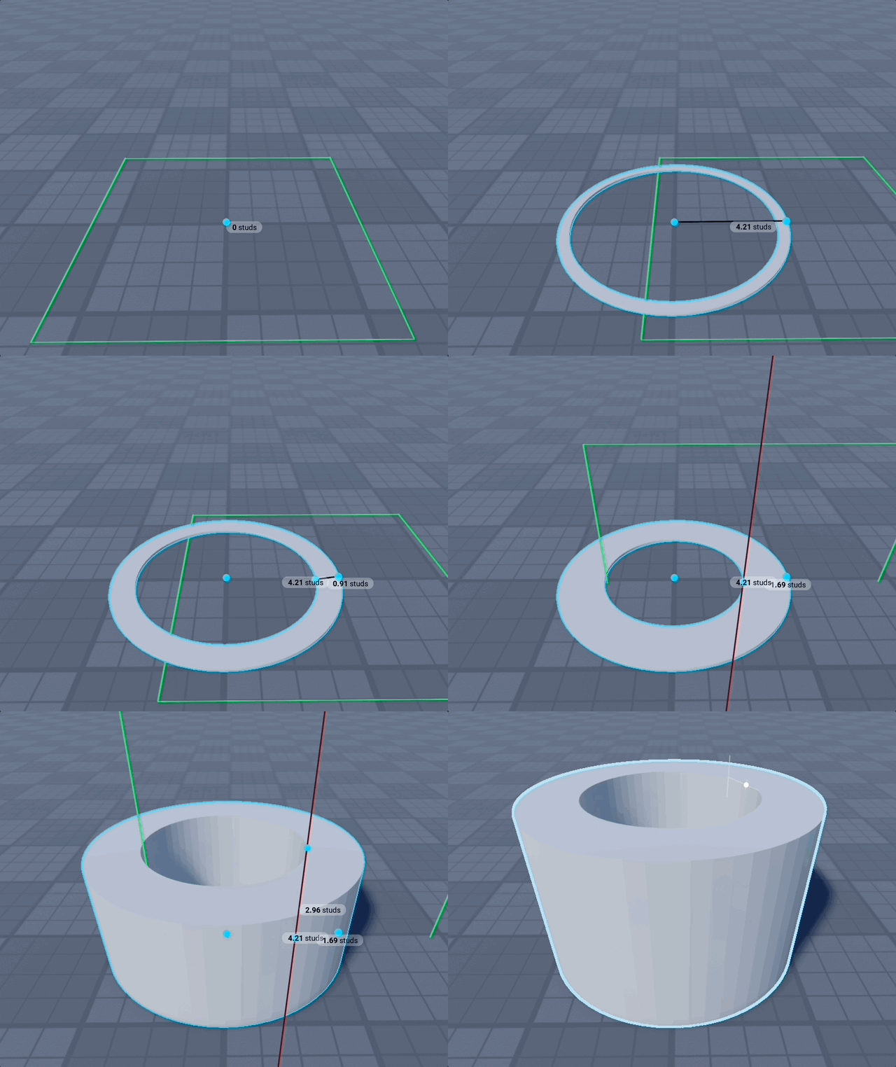
The Donut can be swept all the way round — the classic ring — or only part of the way, which is what an arch is: set the sweep and where it starts and you get doorway tops, half-arches, bridge spans and tunnel rings out of the same shape. There is no separate Arch shape — sweeping the Donut less than the whole way round is the arch.
Quick Shapes
One click on Full donut, Wheel, Doorway, Half ring or Quarter bend sets the sweep, the thickness and the placement mode together. The tag stays lit while the settings still match it, so the row also tells you what you've got — and everything below stays there to tune it further.
Ring Settings
- Sweep (°): how much of the ring to build.
360is a full donut,180a half-arch or doorway top,90a quarter bend. - Start (°): where the sweep begins, measured around the ring. Use it to roll the opening to the side or underneath.
- Thickness (studs): exact studs, measured from the circle you drew. Negative eats inwards from that circle (the way the Donut has always drawn); positive grows outwards from it instead, so the circle you click is the hole — a 10-stud doorway stays 10 studs however thick you make the arch.
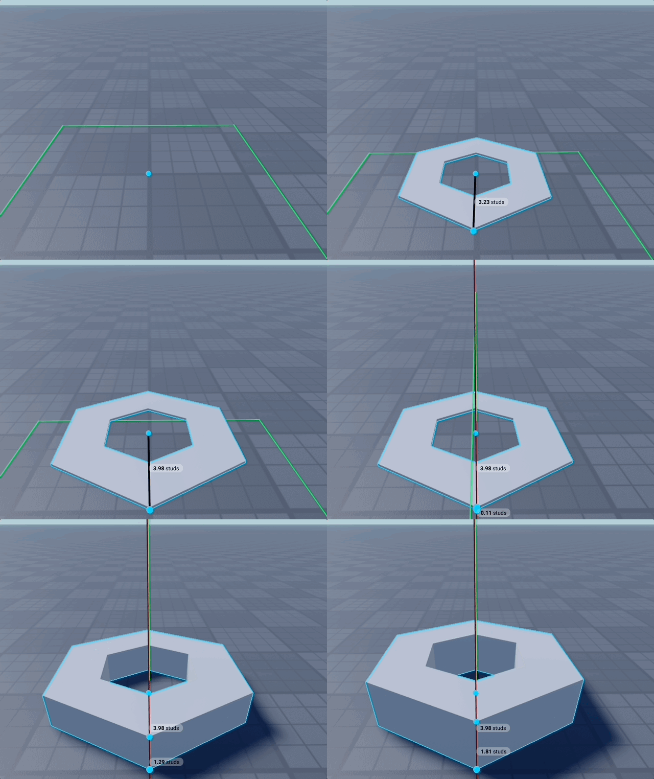
- Segments: facet count for a full circle; a partial sweep uses its share of them. For example, with 60 segments a quarter sweep uses 15. Default is 60.
Here is one with 6 segments:
Placement Mode
- Centre → side: click the centre, drag the radius — the classic flow.
- Start point → end point: click two opposite edges instead. On a partial sweep those are the arch's two feet, so the span you click is the opening.
- Base first (rises off the surface): draw the base flat on the surface and let the ring rise out of it — draw it on the floor and it stands up, no need to find a wall to draw on. A downward-facing surface still arches upwards.
There is no separate Tunnel shape either: the ring extrudes along its work plane's normal, so drawing a partial sweep on a wall pushes it horizontally into a tunnel. Aim at a vertical surface, set the sweep to 180°, and drag the height for the tunnel's length.
Donut demo
Shape - Stairs
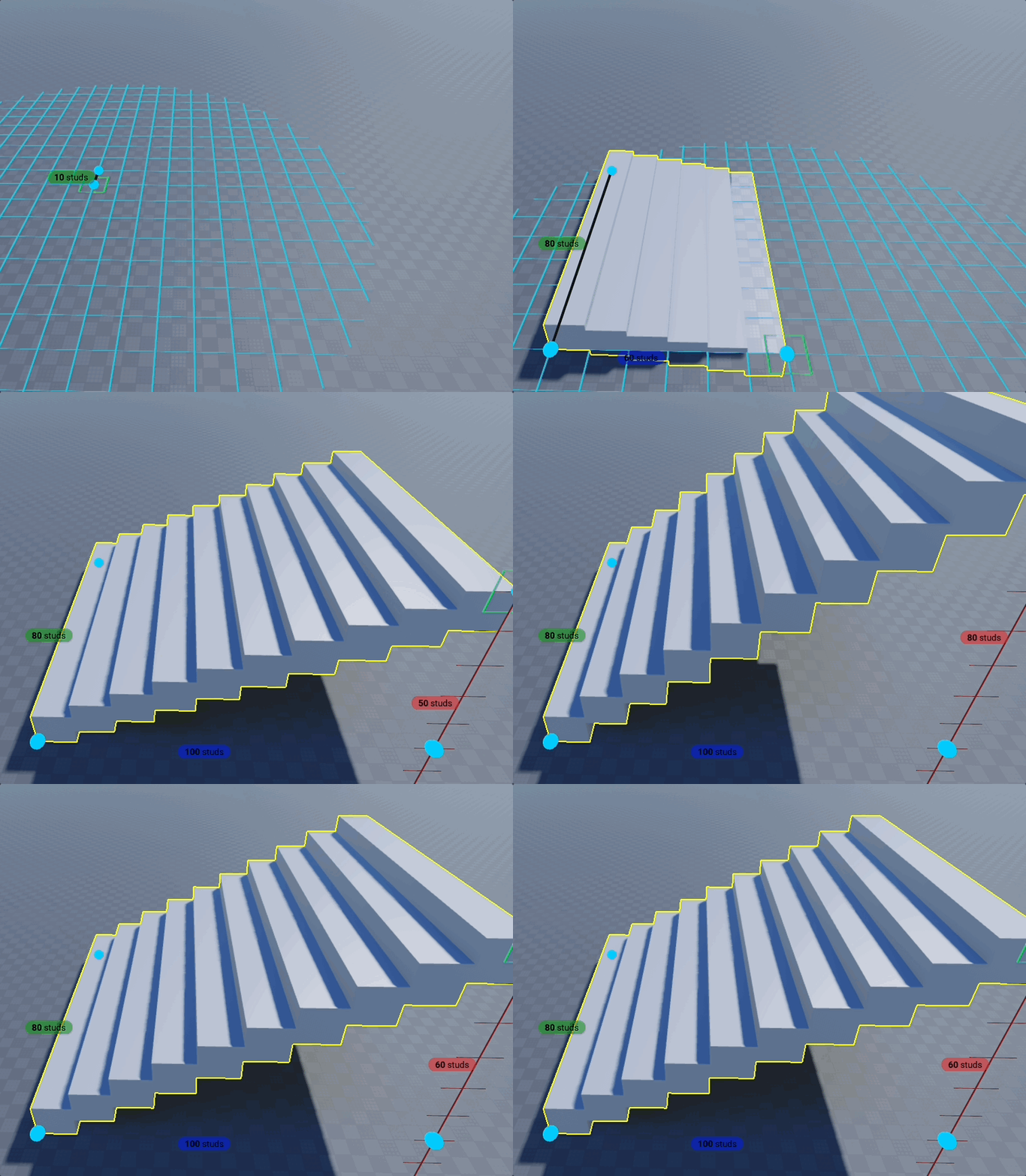
Create diagonal staircases with configurable step dimensions. Steps automatically calculate along the diagonal from the starting point to the height point, making it easy to build staircases of any angle and length. Supports both upward (positive height) and downward (negative height) stairs.
Placement Mode
Width → depth → height
Same draw mode as Block. Click to place:
- First point: starting corner of the stairs base
- Second point: defines the width of the stairs
- Third point: defines the depth of the stairs base
- Fourth point: defines the height where the stairs should end
The stairs will climb diagonally from the base (at the second point) to the height point (fourth point). The height can be positive (upward stairs) or negative (downward stairs).
Width → height → depth
Drags the climb second instead — and the width edge you click is the top of the flight. Click the landing you have to reach, stand the height up on it, and then drag the run out to meet the ground, steeper or gentler, without ever losing the height. The staircase previews at your step size for the whole of that drag, so you see it before you commit to its length.
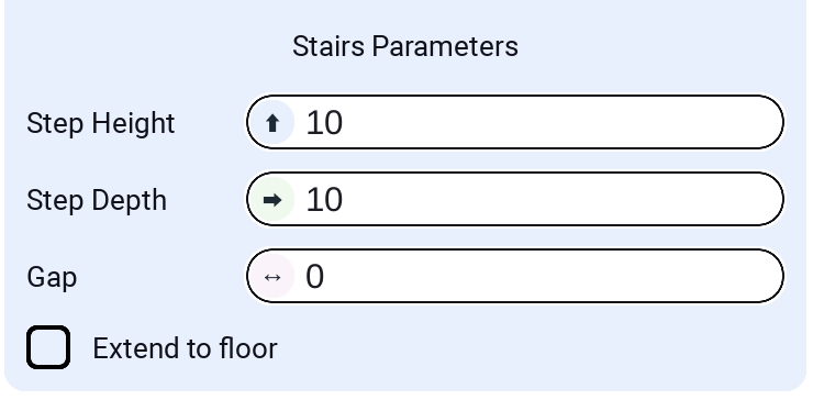
Stairs Parameters
Step Height
The vertical height of each individual step. This controls how tall each step is. Larger values create taller steps; smaller values create shorter, more gradual steps.
Step Depth
The horizontal depth of each step along the diagonal. This controls how deep each step extends. Larger values create deeper steps; smaller values create narrower steps. Steps are spaced by this value along the horizontal projection of the diagonal.
Gap
The gap between consecutive steps. Can be:
- Positive values: Creates spacing between steps
- Zero: Steps are directly adjacent with no gap
- Negative values: Steps overlap, creating a more compact staircase. With step height being small, can create overlapping hovering steps.
Even out steps
The depth you draw almost never divides into whole steps, and the leftover used to show up as slivers of daylight between the treads even with the Gap at zero. Switch this on and every tread grows by the same amount instead, so the steps fill the depth exactly — same number of steps, no unasked-for gaps, and only the Gap you actually set is left between them.
Extend to floor
When enabled, each step extends downward to reach the floor level. For upward stairs, the floor is at the starting point. For downward stairs, the floor is at the ending point. This creates steps that fully connect to the ground, useful for creating more complete stair structures. When disabled, steps only extend to their calculated height.
Shape - Arc
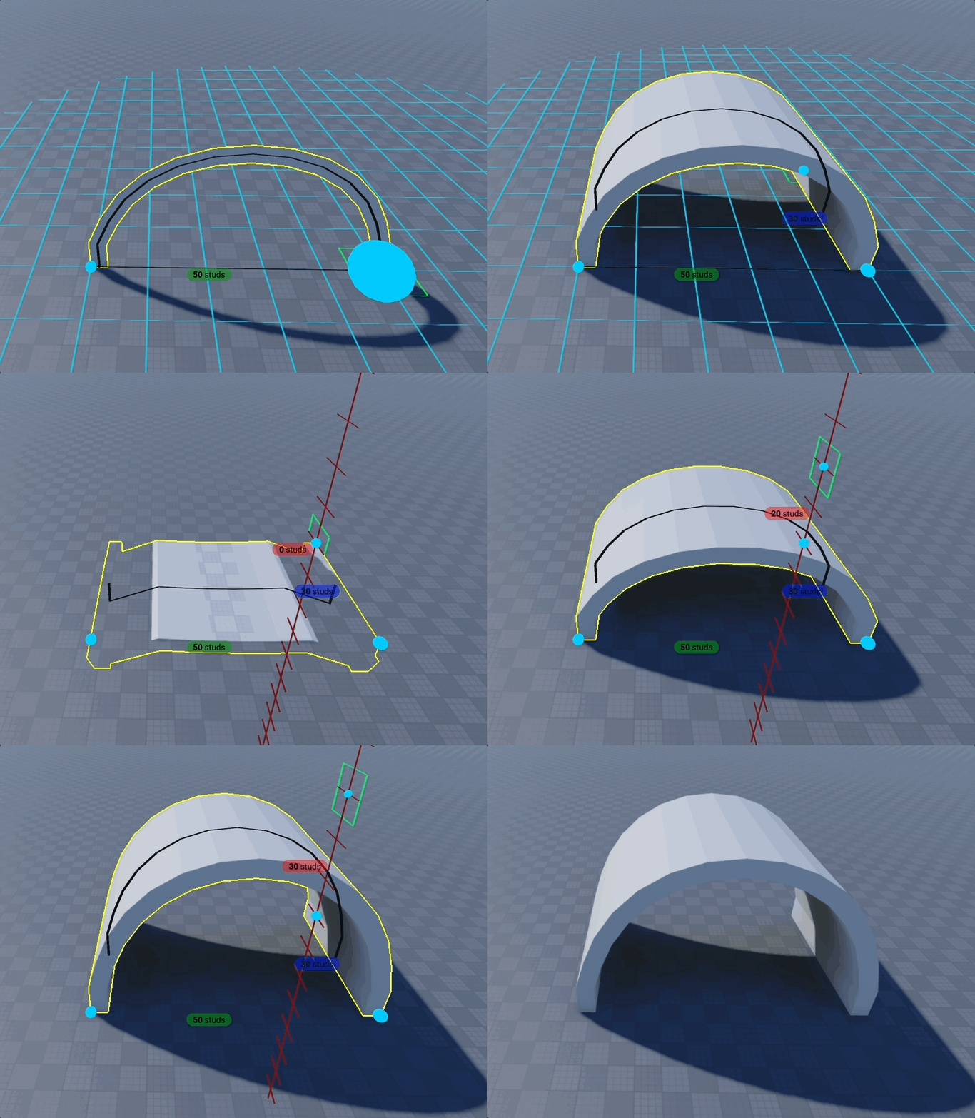
Create smooth curved arches and arcs using cubic Bezier curves. Perfect for architectural elements like doorways, windows, bridges, decorative arches, and curved structural supports.
How to use
- Select the Arc shape from the shape selector
- Place the arc's base according to the Placement Mode below
- Drag the rise (how high the arc curves), then the depth
- Adjust settings in the panel to customize the arc shape — the preview updates live
Placement Mode
Arc picks its own clicks rather than following the block shapes' draw mode:
- Centre → side: click the middle of the arc and one end — the other end mirrors through the centre.
- Start point → end point: click the two ends instead. Both modes then drag the rise and take the depth last.
- Drawn on the surface: the arc is drawn INTO the surface — click the two feet, drag how far the arc bows across the surface, then drag its depth out of that surface (over the work plane or below it). Wall arches and floor inlays, without turning the shape sideways.
Drawing on a downward-facing surface still arches upwards.
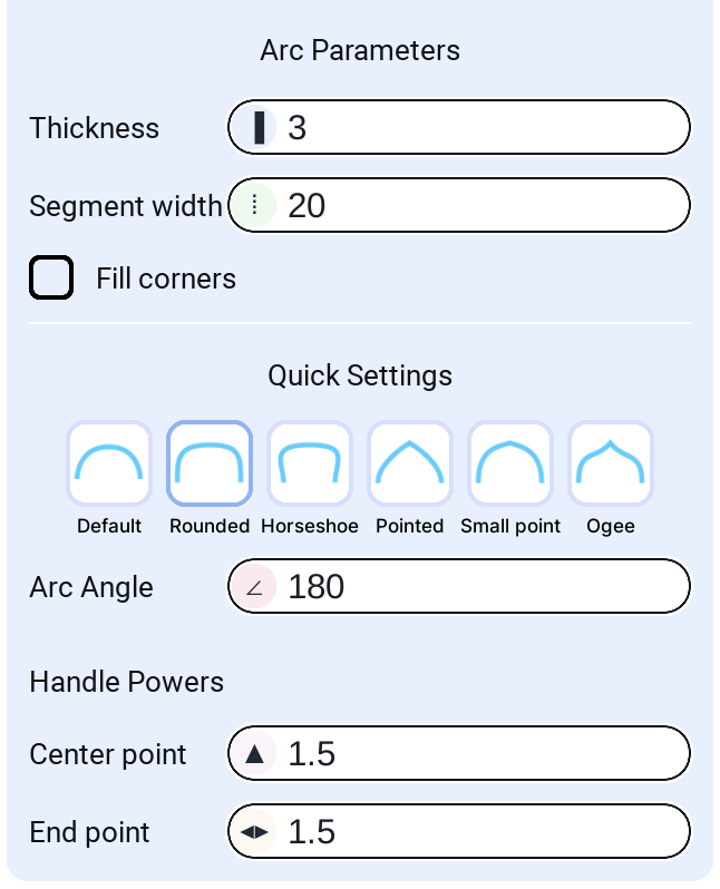
Arc Parameters
Thickness
Exact studs, measured from the arc you drew: positive eats the band inwards, so the arc you draw bounds the whole arch; negative grows it outwards instead.
Base height
Give the arch straight sides and it builds them for you: set how many studs of leg you want under each foot, and the arc springs from there instead of off the ground, with a column of the same thickness and depth filling the gap below it — one drag for a whole archway, instead of two rectangles plus an arc balanced on top. The rise you drag still measures the whole thing, and Fill corners leaves the straight sides to the legs.
Segment width
The width of each individual part along the arc curve. Smaller values create more parts and smoother curves; larger values create fewer, longer segments. This controls the resolution of the arc.
Fill corners
When enabled, fills the corners at the base of the arc with additional geometry for a smoother, more complete appearance. Useful for creating seamless transitions between the arc and its base.
Quick Settings
Choose from six preset arc styles for common use cases:
- Default: A simple, standard arc with balanced curvature
- Rounded: A thicker, more rounded arc with increased handle powers
- Horseshoe: A U-shaped arc with a deep center curve
- Pointed: An arc with a distinct upward point, creating a gothic arch style
- Small point: Similar to Pointed but with a less pronounced point
- Ogee: An S-shaped or wavy arc with elegant curves
Click any preset to instantly apply its angle and handle power settings.
Arc Angle
The angle of the arc in degrees. Controls how much of a circle the arc spans:
- 180°: A half-circle arc (default)
- 90°: A quarter-circle arc
- 360°: A full circle (though typically used for partial arcs)
Range: 0° to 360°
Handle Powers
Control the shape and curvature of the arc using Bezier handle powers:
Center point
Controls the curvature at the top (apex) of the arc. Higher values create more pronounced curves at the center:
- Lower values (0.5-1.0): Flatter, more subtle curves
- Higher values (1.5-3.0): Sharper, more dramatic curves at the top
End point
Controls the curvature at the endpoints (base) of the arc. Higher values create smoother transitions at the ends:
- Lower values (0.5-1.0): Sharper transitions at the base
- Higher values (1.5-4.0): Smoother, more gradual transitions
Adjusting handle powers allows fine-tuning the arc shape beyond the preset styles. Experiment with different combinations to achieve the exact curvature you need.
Shape - Curve (Bezier Path)
Create smooth curves by placing anchor points. The plugin generates parts along the path using smooth Bezier interpolation. Perfect for roads, pipes, rails, decorative lines, and any organic flowing geometry.
How to use
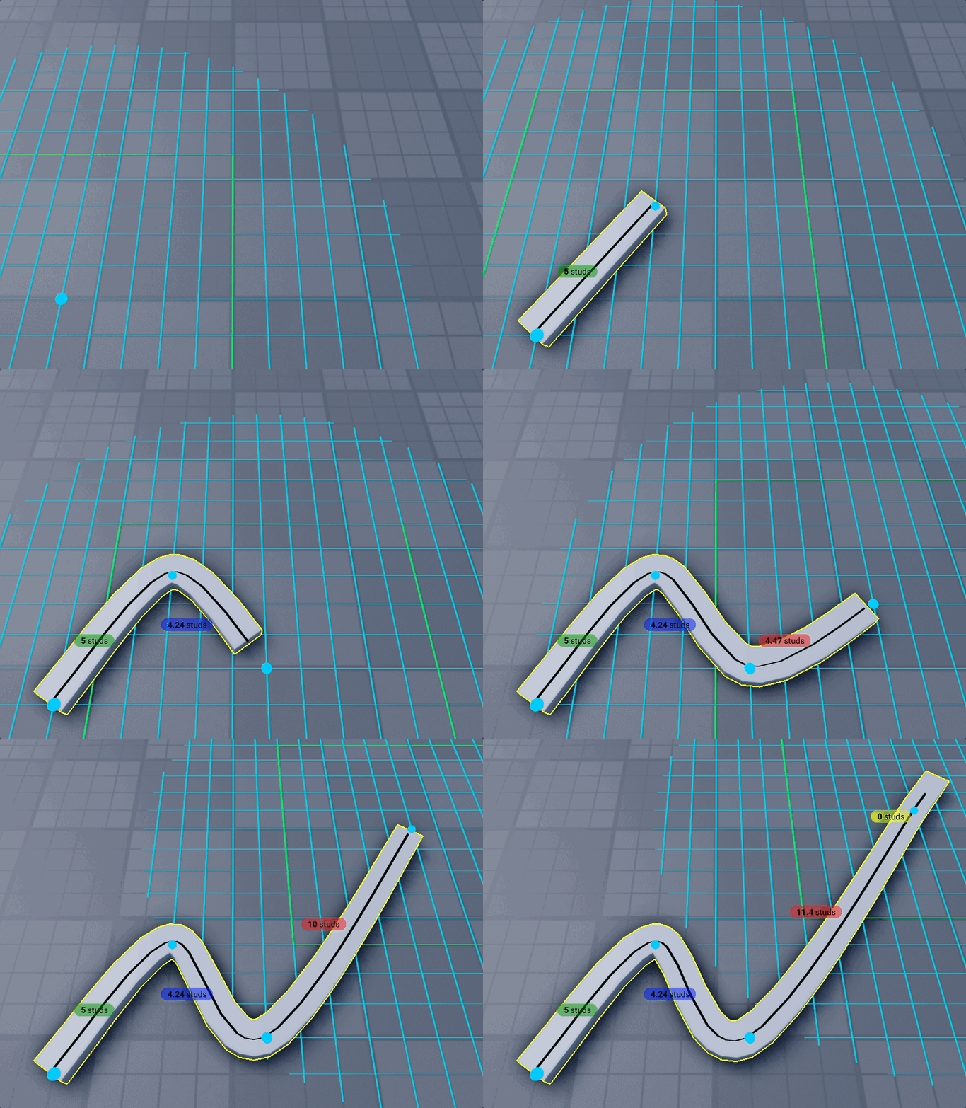
- Select the Curve shape from the shape selector
- Click to place anchor points (minimum 3 points required)
- The curve automatically smooths between points using Catmull-Rom interpolation
- Adjust settings in the panel as you place points
- Press Space or click "Finish Building" to complete
Settings
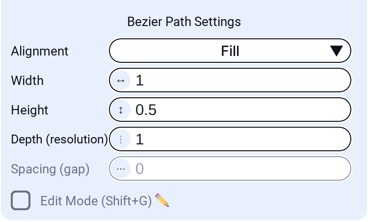
Width
The width of each generated part along the curve. This is the horizontal dimension perpendicular to the curve direction.
Height
The height (vertical thickness) of each generated part. Adjust for thicker rails, roads, or thin ribbons.
Depth (resolution)
The length of each individual part along the curve direction. Smaller values create more parts and smoother curves; larger values create fewer, longer parts.
Spacing (gap)
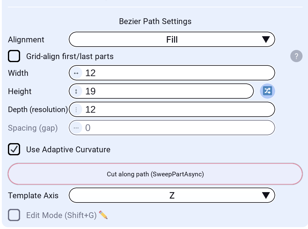
The gap between consecutive parts along the curve. Set to 0 for continuous geometry with no gaps. Disabled for Fill and Touch alignment modes since those modes determine spacing automatically.
Alignment Modes
Control how parts are positioned and distributed along the curve:
Center
Parts are centered along the curve path. Even spacing with gaps between parts.
Left
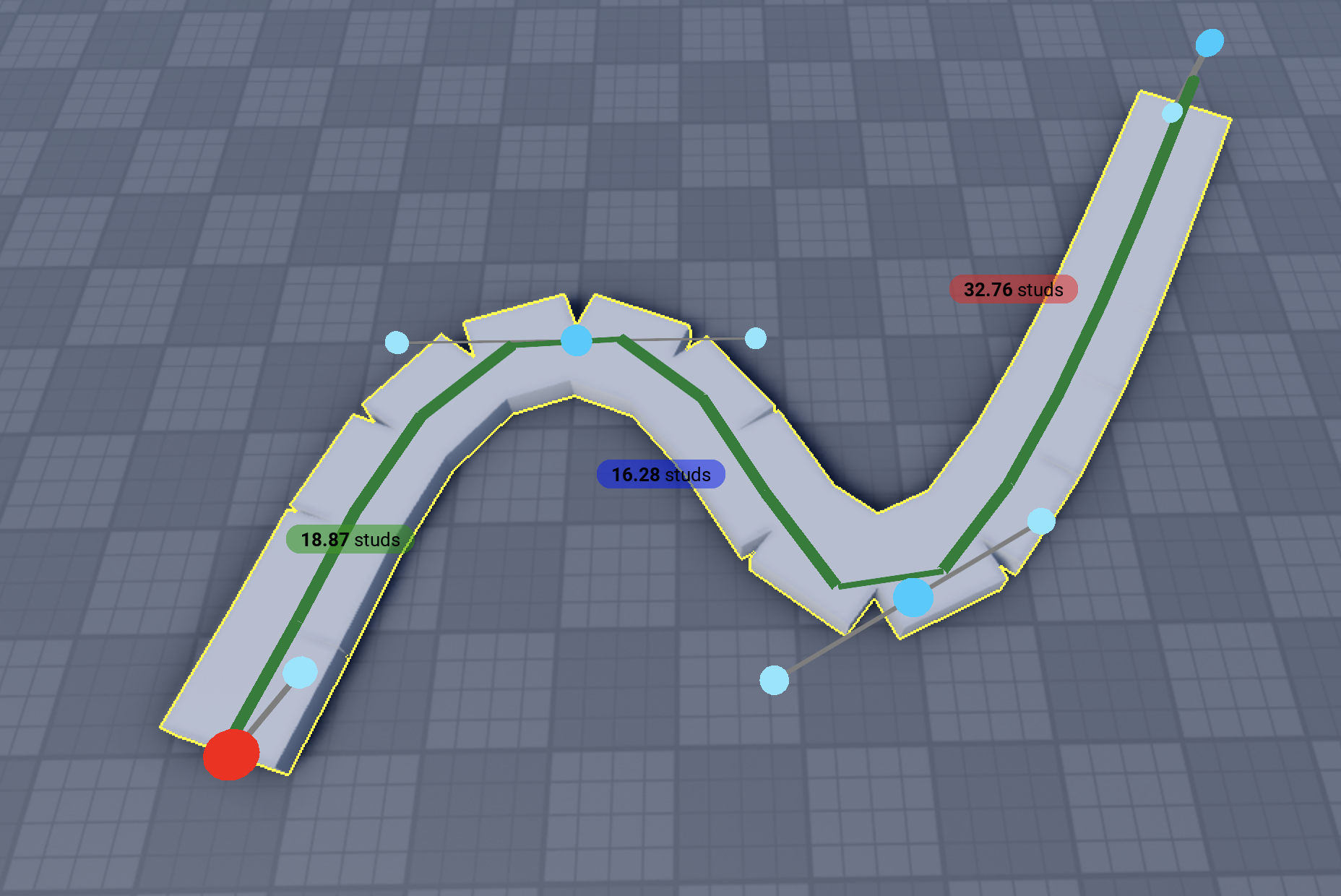
Parts are aligned to the left edge of the curve. Useful when building along a wall or boundary.
Right
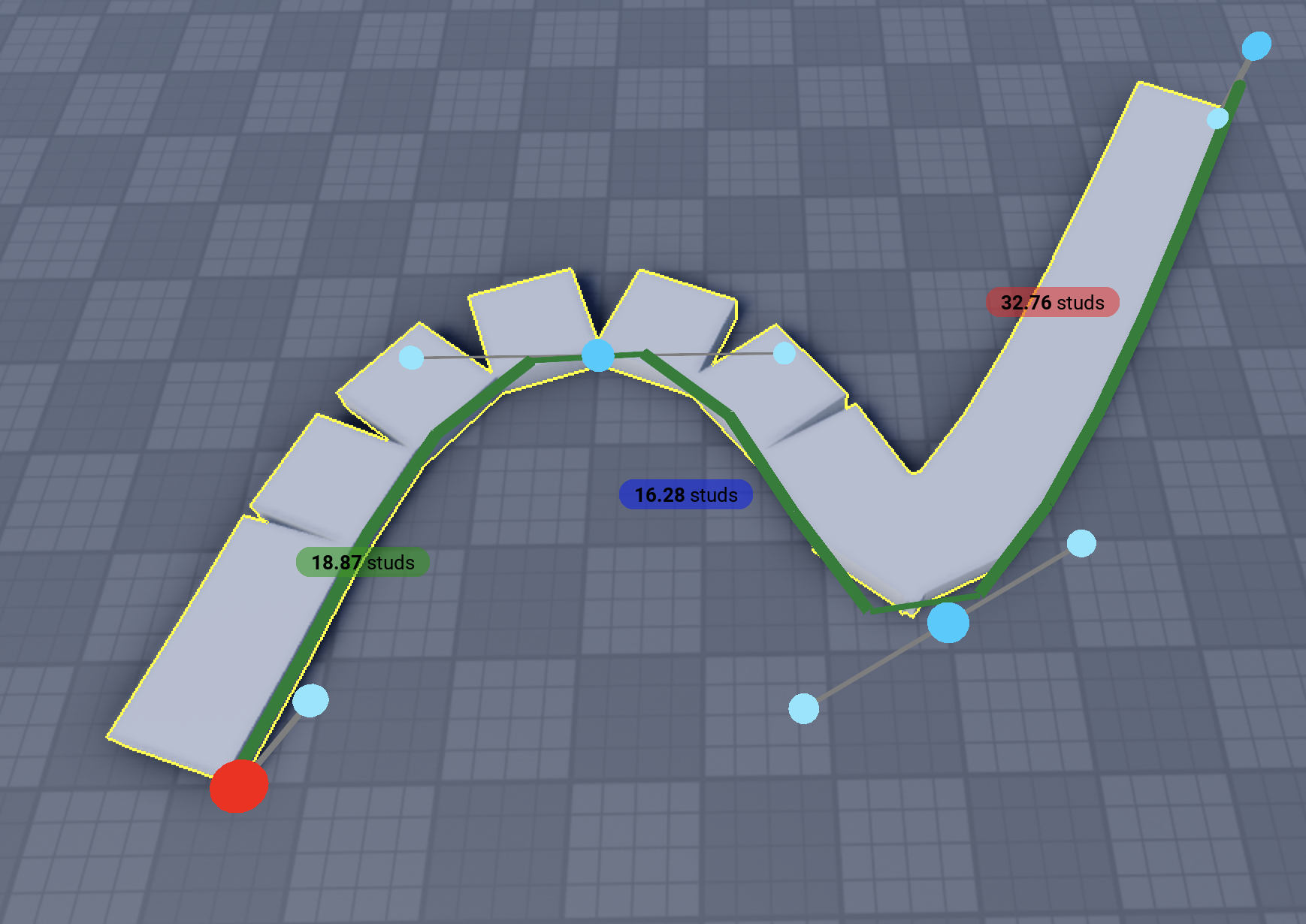
Parts are aligned to the right edge of the curve. Mirror of Left alignment.
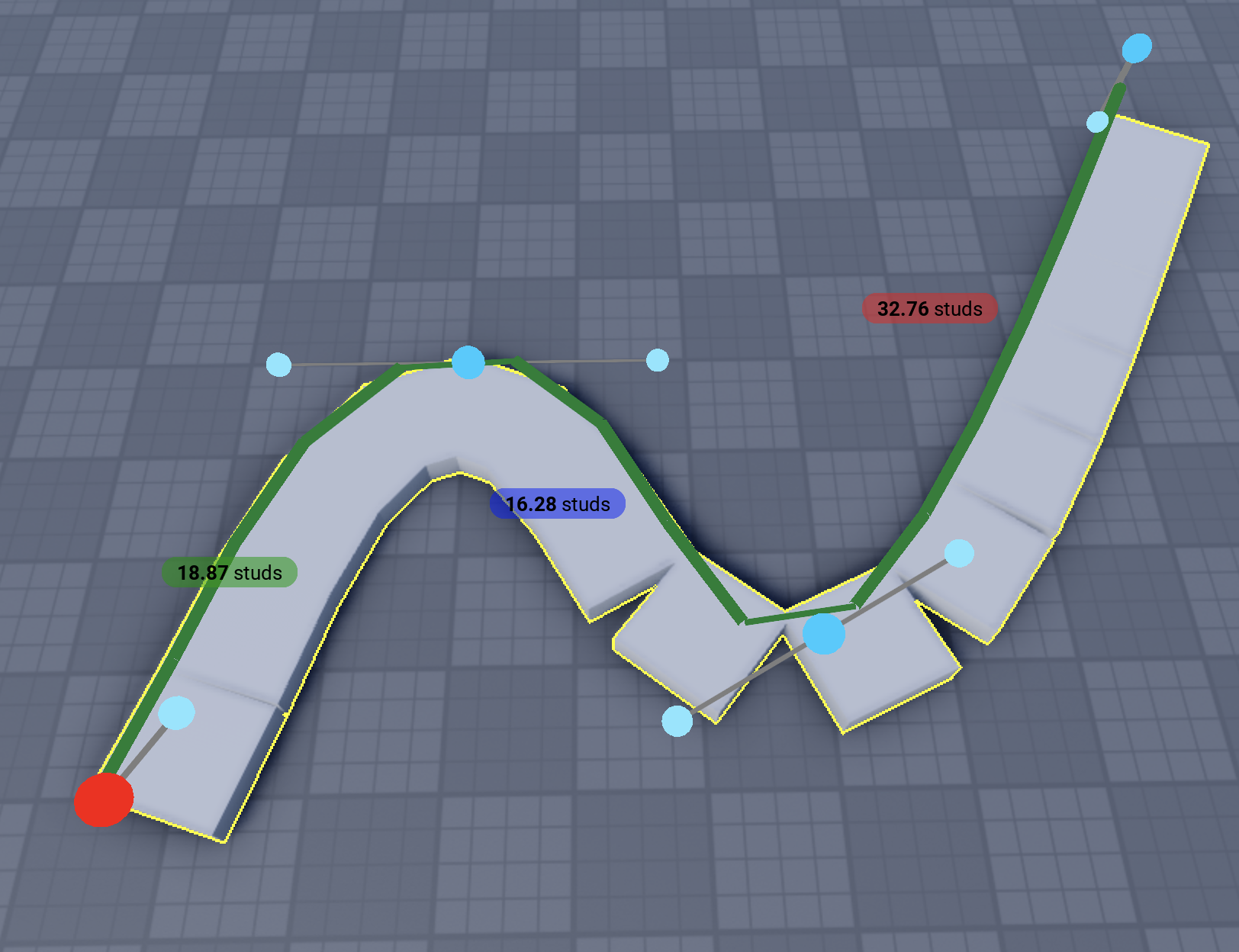
Fill
Parts stretch to completely fill the curve with no gaps. Uses parallel transport framing for smooth, twist-free orientation. Creates a continuous ribbon effect—perfect for roads or platforms.
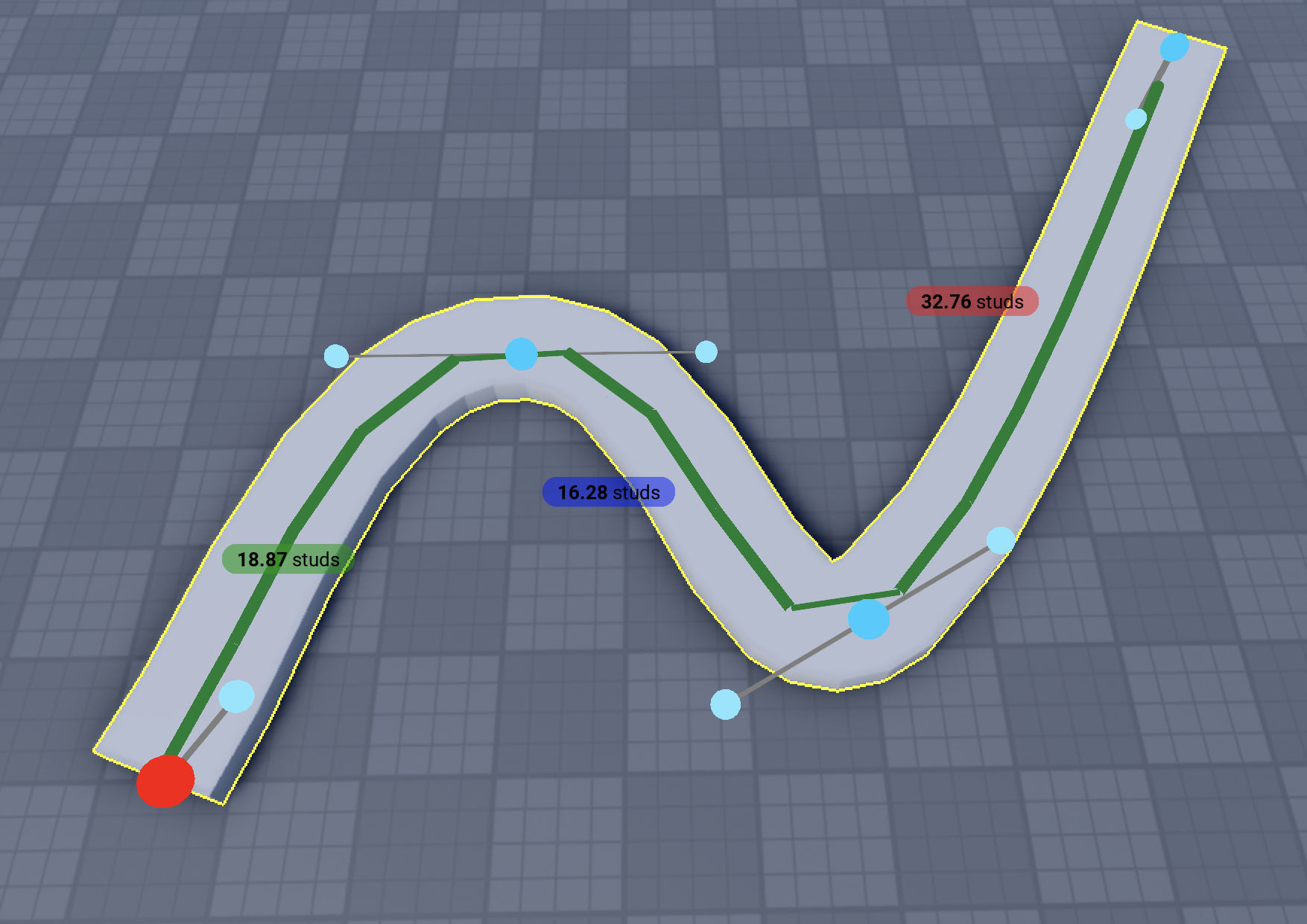
Use Adaptive Curvature: When enabled, parts become smaller at curves by creating denser sampling at sharp corners. This results in smoother curves with better visual quality at bends. Enable this option if you want parts to be smaller at curves for smoother appearance.
Touch
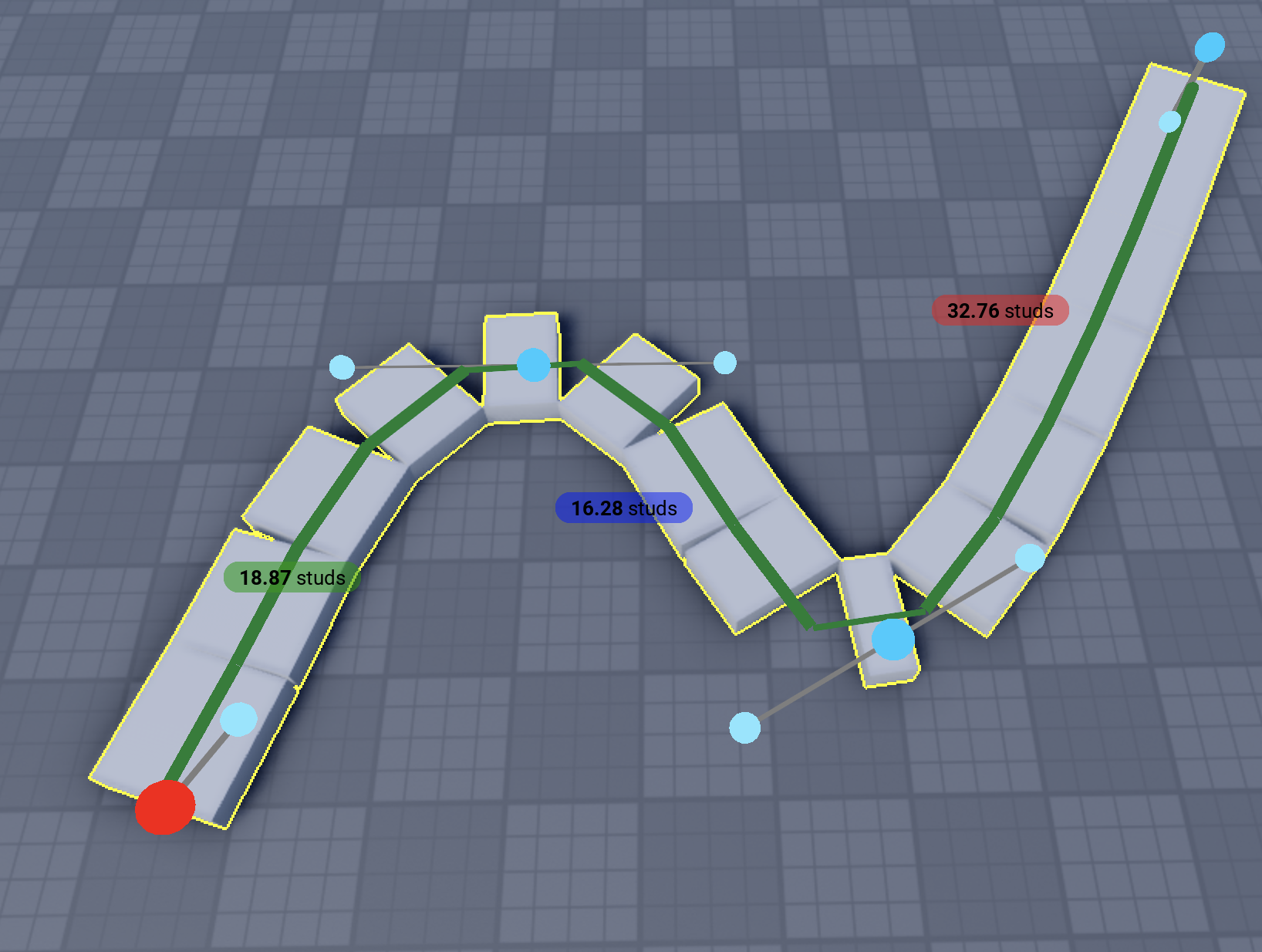
Parts are sized so adjacent parts touch exactly at their edges. Uses adaptive curvature sampling to add extra parts at sharp corners. Good for segmented paths that need to look connected.
Template Support
You can use a selected Part or Model as a template instead of simple rectangles. The template is repeated along the curve, following its orientation.
When a template is selected, the Template Axis dropdown appears:
- Z / -Z: Template's Z axis follows the curve direction
- Y / -Y: Template's Y axis follows the curve direction
- X / -X: Template's X axis follows the curve direction
This lets you orient models correctly regardless of how they were authored.
Cut along path
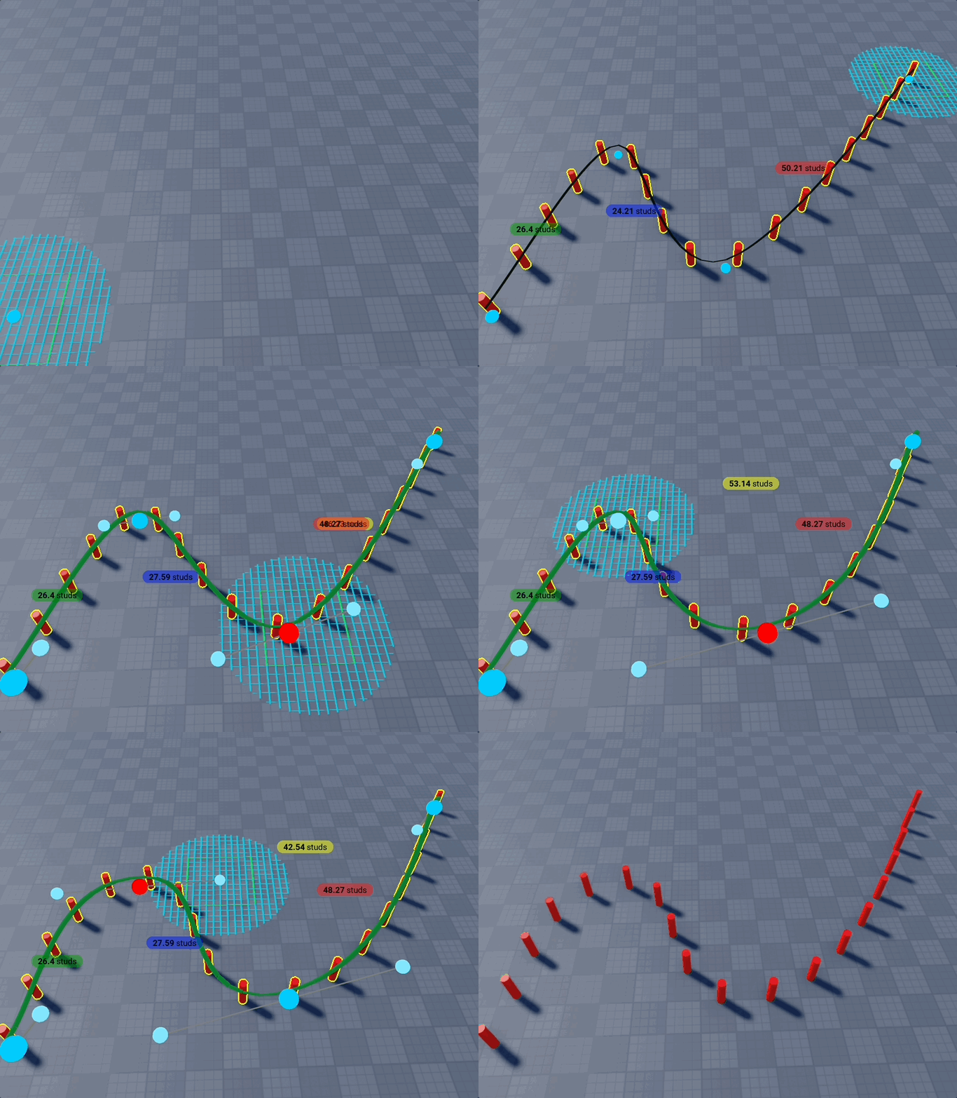
After placing at least two points on a Bezier path, you can subtract a swept cut from touching parts using the red Cut along path (SweepPartAsync) button at the bottom of the Bezier Path settings block.

Requirements
- Select a BasePart as the template (in Template settings). Models are not supported for this action.
- Place at least two anchor points on the curve.
- The cut uses the same path sampling as the live preview (width, height, depth, alignment, and optional grid-aligned endpoints).
What it does
- Samples the current Bezier path into sweep frames (matching how parts would be built along the curve).
- Sweeps the template part along those frames via
GeometryService.SweepPartAsync. - Subtracts the resulting hull from sliceable parts (same scope as Punch: all touching parts or only selected, per your cutter settings).
Use this to carve grooves, slots, or tunnels along a curved guide without building placeholder parts first.
SubtractAsync cut results are mesh-backed parts. Save or publish each resulting mesh to Roblox from Studio before publishing your experience. See the Tools dock warning for the full workflow.
Curve Library
The Curve Library accordion lists ready-made Bezier presets you can place in one click:
- Closed 2D: Circle, Rounded Square, Capsule, Star, Heart, Infinity ∞
- Open 2D: Half-circle, Wave
- 3D: Spring (helix)
Click Build on a preset to start placement on the active work plane. Adjust radius with your mouse, then commit like any other shape.
Save current curve: While in Bezier edit mode, use Save current curve… to store the active path under a custom name. Saved curves appear in the same list for quick reuse.
Edit Mode
Enable Edit Mode (Shift+G) to interactively adjust the curve after placing points:
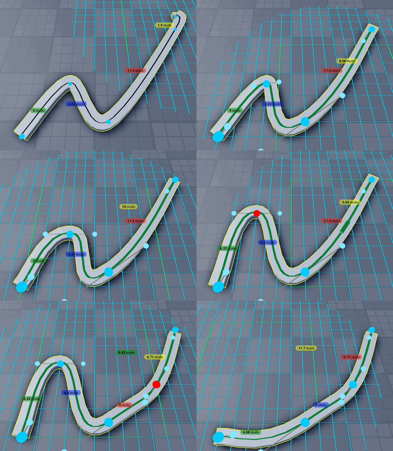
- Move point: Click & drag any anchor point to reposition it
- Delete point: Select a point (turns red) then press Backspace/Delete
- Add point: Click on an edge between anchors to insert a new point
- Resize bounding box: Drag the box handles (with axis rods) to scale the whole curve
- Rotate: Use the rotation handle on the bounding box to spin the curve in the work plane
- Size labels: W, H, and D labels show the bounding box dimensions while edit mode is active
The curve updates in real-time as you edit, making it easy to refine paths. Sharp bends automatically get triangle bevels so tight corners stay visually clean.
3D Curves
The Bezier Path supports 3D curves. Place points at different heights and the curve will smoothly interpolate through all of them. The parallel transport algorithm ensures parts maintain consistent orientation without unexpected twisting.
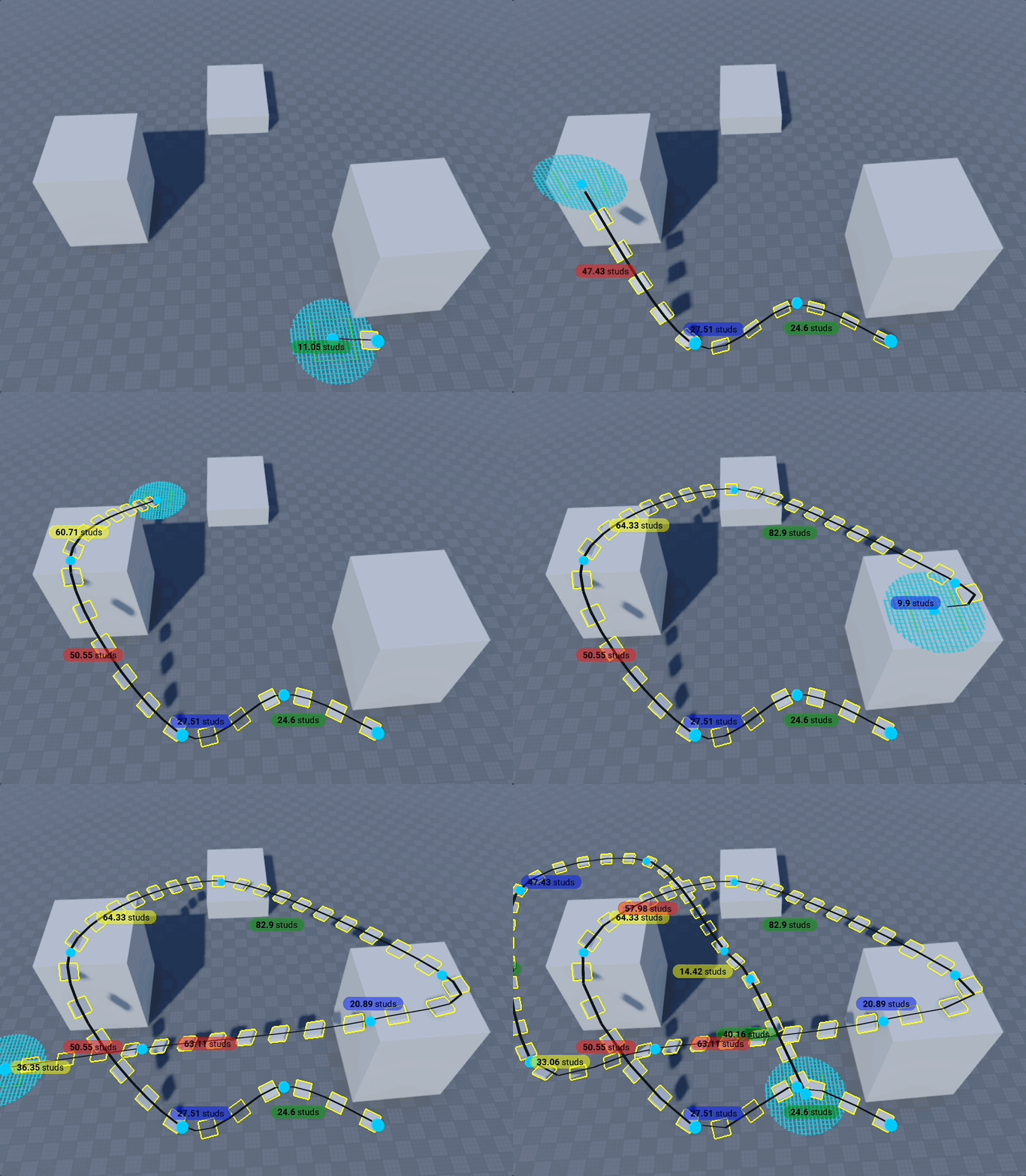
Banking (leaning the path into a turn): select a control point in Edit Mode and Studio's own Rotate gizmo appears on it. Rolling the point about the direction the curve travels leans the ribbon over there — a banked corner, a cambered road, a rolling barrel of track — and the lean eases back to level towards the neighbouring points. The Bank readout above the point shows how far it is leaning. Rotating the point any other way steers the curve rather than tilting it: it swings the tangent, so the path bends through the point while every cross-section stays level.
Set Studio's Rotate gizmo to Local space before banking. In Global space the rings are locked to the world axes, so unless the curve happens to run straight down one of them there is no ring that rolls about the path — you can only pitch and yaw the point, and the Bank readout stays at 0°.
When using Fill mode with 3D curves that change elevation, there may be small gaps between parts. Perfect gap-free surfaces in 3D would require additional wedge and corner-wedge parts, which is not currently implemented. For best results with elevation changes, use smaller Depth values to minimize visible gaps, or use Touch/Center modes with spacing.
Shape - Line
Draw a path of connected straight segments — a road, wall, fence, curb, or pipe run — by clicking to place points. Each segment is built as its own part, and every turn between segments is shaped by the Corner Type. With no template, Line builds a plain box per segment sized by Height & Width, so you don't need to prepare any geometry first. Point a Part or Model template at it (in Template Settings) to build from that shape instead.
How to use
- Select the Line shape from the shape selector.
- Click to place points. A straight part is drawn between each pair of consecutive points, updating live as you move the mouse.
- Adjust settings (Height, Width, Corner Type, alignment) while placing — the preview updates.
- Press Space to close the loop (connect the last point back to the first), or click Finish Building to end an open line.
Part Settings (plain mode)
When there is no template (or "Copy shape" is off), each part is a plain box:
- Height: Vertical thickness of each segment part.
- Width: Horizontal width of each segment part, perpendicular to the segment direction.
Corner Type
Choose how each turn between two segments is shaped:
- None: Segments simply meet; no extra corner geometry.
- Sharp: A mitered joint that fills the wedge between the two segments for a clean, solid corner.
- Round: A cylindrical corner that rounds the turn.
- Bevel: A flat, angled corner across the turn.
- Bevel inner corner: Also bevel the inside of the turn. When on, Amount sets the bevel segment length.
- Chamfer: A cut corner. Amount sets the size of the cut.
- Curve: A smooth, multi-part arc around the turn.
- Length: How far the segments pull back to make room for the arc. The two corners at either end of a straight share its length between them — whatever the far end doesn't need (because it is the end of the line, or a smaller turn), this corner can have, right up to the whole run. Where both want more than there is, they split it.
- Resolution: How many parts form the arc — higher is smoother.
- Build with:
- Exact: the curve as wedges shaped to the bend, so the road keeps its real edges the whole way round.
- Blocks only: one plain box per facet, each grown a little at both ends so it buries itself in the block beside it and in the two straights — a quarter of the parts for the same curve, with the overlap hidden inside solid parts. The outer edge becomes a run of flats sitting just outside the true curve, so raise Resolution if you can see them.
Corner rounding lines up best with the None corner alignment.
Corner Alignment
Controls how parts meet at a turn (applies in every mode): Outside, Inside, Fill, Touch, or None.
Building from a template
Pick a Part or Model in Template Settings to build the line from an existing shape instead of plain boxes.
- Part template — Copy shape: With "Copy shape" on, each segment adopts the part's shape, size, and look, and the corner fillers match its look. Turn "Copy shape" off to keep plain boxes of your own Height & Width that only wear the part's look.
- Model template: The model is cloned along the path. Model turns are resolved by Magic Merge (with an optional Clean up small parts after merge) rather than the Corner Types.
- Placement Mode: None, Copy, or Stretch — how the model repeats or fits along each segment.
- Extend to mouse position: Stretch the current segment out to the cursor.
- Spacing: Gap (studs) between repeated copies.
Edit Mode
Enable Edit Mode (Shift+G) to adjust a placed line after the fact — on both plain and template lines, just like Polygon and Curve:
- Move point: Click & drag any point to reposition it.
- Add point: Click a segment to insert a new point.
- Delete point: Select a point (it turns red) then press Backspace/Delete.
Closing the loop with Space while drawing automatically drops you into Edit Mode.
Shape - Pipe
Draws exactly like a Line, but every run is a cylinder instead of a box — pipes, cables, handrails, tubes, and conduit, with no template to prepare. Every bend is sealed with a sphere, so an elbow reads as a real pipe rather than two tubes crossing.
Point placement, Edit Mode, loop closing, and the grid/work-plane behaviour all match Line.

How to use
- Select the Pipe shape from the shape selector (next to Line).
- Click to place points. A cylinder is drawn between each pair of consecutive points, updating live as you move the mouse.
- Set the Diameter while placing — the whole pipe updates, not just new runs.
- Press Space to close the loop, or click Finish Building to end an open run.
Pipe Settings
- Diameter: Thickness of the pipe, across both axes — runs stay perfectly round, and the joint spheres match.
- Round ends (off by default): Caps each open end with a sphere, turning the pipe into a cable, handrail or rod. The cap sits on the end point, so the run reaches half a diameter past it — leave it off to butt a pipe flush against a wall, and note that a closed loop has no open ends to cap.
That is the whole panel. Pipe is deliberately a near-one-knob shape: the corner alignment, corner type and spacing that Line exposes are fixed here to the one combination that makes a pipe look like a pipe — runs meeting at each point, sealed with a sphere, no gaps. If you need to vary any of those, build it with Line instead.
Templates
Pick a Part in Template Settings to copy its colour, material and decals onto the pipe. The pipe always keeps its round shape — a Part template is a look donor only, and Model templates aren't used by this shape (use Line for those).
Line can build round runs too: set a cylinder Part as its template and turn on Copy shape. You then get every Line corner type on a round cross-section, including the Curve swept elbow.
Shape - Truss
Draws like a Line, but every run is a climbable TrussPart — ladders, scaffolding, catwalk frames and lift shafts.
Point placement, Edit Mode and loop closing all match Line.
Truss Settings
- Style: Alternating is the classic zig-zag ladder, Bridge adds crossed supports for a heavier scaffold look, and Plain drops the diagonals, leaving just the rails and rungs.
- Corner Alignment: how two runs meet where the path turns. A truss has no corner filler, so this is the corner's look. Touch (the default) pulls each run back so they just meet — at a right angle that is exactly half the truss width. None lets both runs reach the corner point, which overlaps them and doubles the lattice there.
Roblox fixes a truss's cross-section at 2×2 studs, so only its length follows your clicks — draw straight up for a ladder, or along the ground for scaffolding.
A single truss run can't exceed 512 studs; the engine caps it. Place an extra point to carry on past that.
Shape - Stamp
A stack-on-face tool: hover any part's face and click to create a new part that matches that face's footprint, extruded outward along the face normal. Perfect for quickly building up greebles, ledges, caps, and stacked details without measuring.
How to use
- Select the Stamp tool from the shape selector.
- Hover the face of an existing part — a preview appears matching the face footprint.
- Click to commit the stamped part.
Blocks stay blocks and cylinder caps stay cylinders, so the new part inherits the hovered face's shape and footprint automatically.
Wedges work too: hover either triangular side of a wedge and the stamp is another wedge with the same slope, continuing the ramp sideways. A wedge's flat faces (its base and its tall back) stamp as blocks like any other rectangle.
Settings
Height (studs)
How far the new part is extruded outward from the hovered face along its normal.
Lip (widen on all sides)
When enabled, the stamped footprint grows outward by a configurable number of studs.
- Lip (studs): How far the footprint extends beyond the original face on each side.
Dynamic lip (toward hovered edge)
When enabled, the lip overhangs only the edge or corner under the cursor instead of widening every side. Hover the center of the face to widen all sides, or hover near an edge/corner to overhang in that direction — useful for ledges and overhangs.
Stop at blocking parts
Off by default, the stamp takes the whole face it is pointed at. That is what you want for a ledge or a cap, and exactly what you don't want for wallpaper: the walls of a room overlap at their corners, so a stamp on one wall's inner face runs straight through the two walls beside it and out of the building.
Switch this on and the footprint is trimmed back at whatever already stands in its way. The stamp is measured at full size, everything reaching into that volume is projected onto the face, and what you get is the largest clear rectangle still containing your cursor — so a panel on an inner wall stops at the walls at either end, and a panel on the wall above a doorway stops at the door frame.
Parts you stamped earlier count as blockers too, which is what makes a run of stamps tile a room instead of piling up at every corner. Fully transparent parts do not — the clip is about what shows. Blocks only: a cylinder cap's footprint is its diameter and a wedge's is its profile, so trimming either on one side would change the shape rather than shorten it, and both are left whole.
If your cursor is over a spot that is already blocked, there is no clear rectangle to grow out from — the stamp stays whole rather than guessing which side you meant. Point at the open part of the face instead.
Demo of different shape types
Demo of building something random
Defining height demo
Demo for Wedge and Snap to Part
Shape - Voxel
A grid-cell extrusion tool: hover a cell on the work plane and drag up to stack blocks; hover the top of an existing block and drag down to carve cells away. Great for fast terrain, walls, and blocky structures aligned to the grid.
How to use
- Select the Voxel tool from the shape selector.
- Hover a grid cell — a green ghost shows how many cells you will add.
- Drag up and release to extrude blocks.
- Hover the top of a block you created — a red ghost shows removal.
- Drag down and release to remove cells from that column.
Blocks are placed relative to the current work plane and grid size, not the world axes.
Settings
Optimize resulting blocks
When enabled, adjacent same-height blocks with matching material merge into larger rectangles after each add. No CSG — only axis-aligned boxes. Wedges are excluded from merging.
Advanced building
When enabled, where you hover inside a cell picks the extruded shape:
- Cell center: a plain block (default behavior).
- Near an edge: a wedge rising at that edge.
- Near a corner: a corner wedge peaking at that corner.
Hover a wedge's top edge (or a corner wedge's peak) to resize it — drag to zero to remove it.
Related
- See Common Settings for shared options across builders
- See Keyboard Shortcuts to work faster